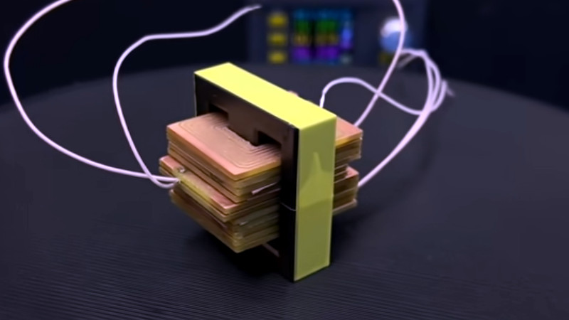
Those readers who have experimented with winding their own inductors will know that it’s not an easy task, and when those inductors are handling high voltages it can be especially tricky to maintain adequate insulation between layers of windings. [Open Frime TV] has a video addressing this in a novel way, by creating the windings for a switch-mode power supply transformer using stacked PCB coils instead of wire (Russian language; you’ll have to enable YouTube’s subtitle auto-translation).
You can always order your PCBs at JLCPCB
The video below the break makes for a handy primer on PCB coil construction, reminding the viewer that the turns need all to lie in the same direction as well as the importance of insulation between windings. There’s a discussion of the properties of a PCB coil in relation to the switching frequency, and once the transformer has been assembled, we see it hooked up to a power supply board for a test. What happens next may be familiar to seasoned transformer-winders; nothing works, and the transformer gets hot. In making the PCB he’s left some copper on each board which amounts to a shorted turn — cutting these allows the transformer to work perfectly.
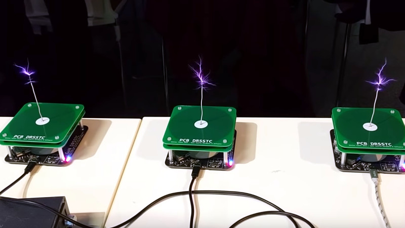
This technique might not be the solution to all transformer woes, but makes for an interesting option if your work takes you in the direction of winding transformers. If PCB coils take your interest, how about a Tesla coil using them as in this picture from a previous post?