The nRF52840 is such a flexible and easy-to-use SoC for BLE devices that we ended up using it in a lot of our projects lately at Zalmotek - from wearables to remote controllers, or other sensing devices that needed sending data to a phone or to BLE devices nearby.
The Raytac MDBT50Q-1M SoM is a great choice for the nRF52840 SoC since it provides everything you need in a compact package and breaks out enough pins to do anything you need on the I/Os.

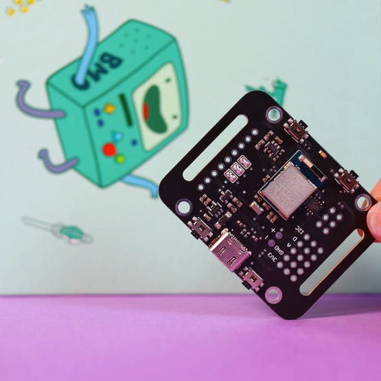
Watch-shaped BLE wearable with a display, 4 push-buttons, USB type C charging, and programming port, LiPo Charging module, and a few IO pins.
Adafruit’s Feather nRF52840 Express is a great testbed to start with and try out the proof of concept, but after successful testing, we usually need a few more features around it. So we created our custom PCB to encapsulate that. Push buttons and a small screen are always needed so we built around that, also adding LiPo battery charging features.
Another benefit of building on top of Adafruit’s development board was the amazing documentation and the helpful community that already developed a handy bootloader that you can use to code directly in the Arduino IDE.
For the display, we wanted something battery efficient and easy on the eyes and the Adafruit Sharp Memory Display was a very good choice to go for. Battery life is great, even too good if we can say, with a 40mAh LiPo battery running the Hello World on the display with the board the device went for
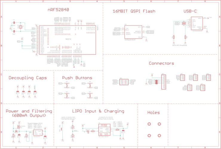
Here are the main functional blocks of the device:
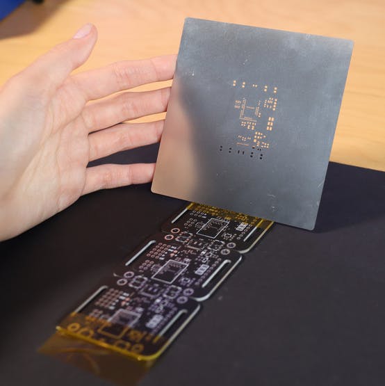
We've ordered the PCBs from PCBWAY in matte black, along with a custom-sized stencil, which is smaller and easier to use than the default sized one. Perfectly applied solder paste! Next, we've carefully placed the components and soldered the PCB using our DIY reflow oven (which uses a Rocket Scream controller).