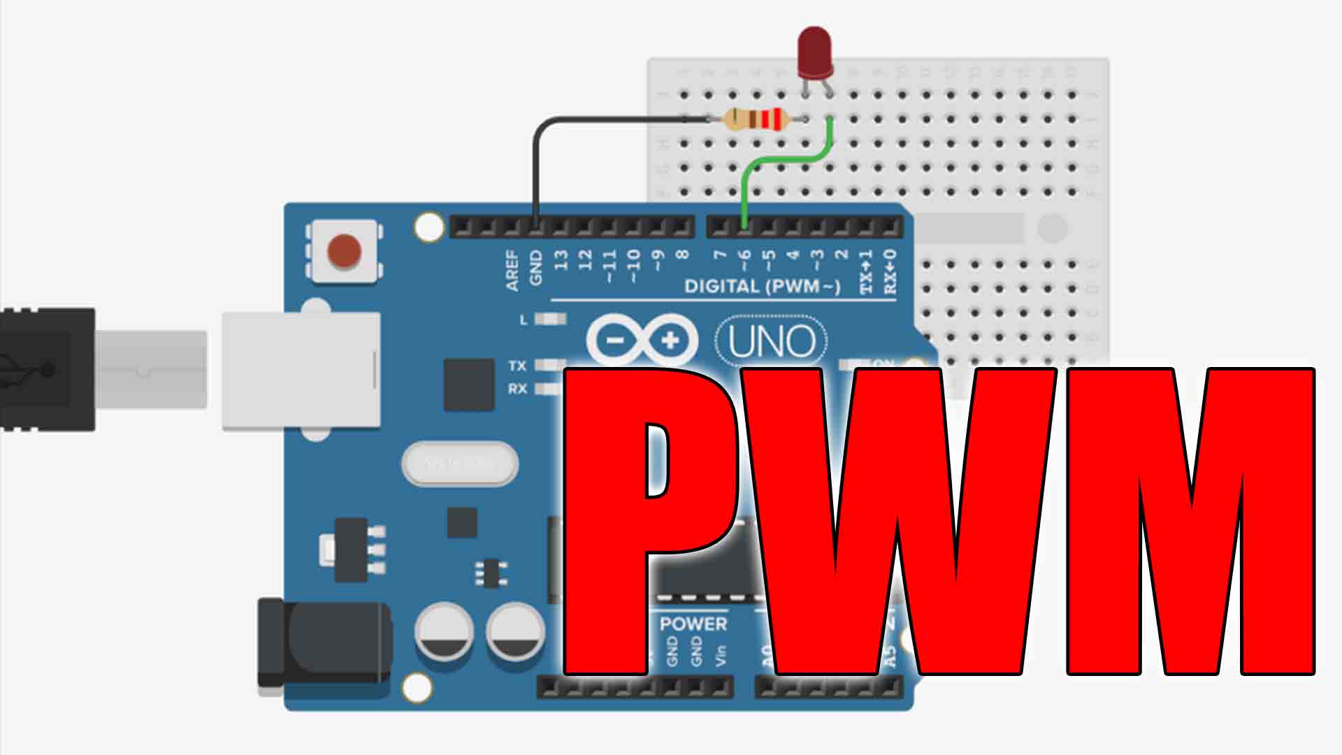
If you’re like us, you spend a lot of time prototyping new projects, starting with a breadboard, a handful of jumper wires, and whatever microcontroller seems to be an ideal fit for your vision. But there is something about the breadboard that feels unfinished.
This really left us thinking: How can we create a quicker path to PCB for all who design with the open-source hardware we have come to love? So we looked at the projects we’d built and found commonalities in the circuits, which we then used to create a pre-built, verified, ready-to-use template.
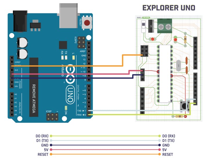
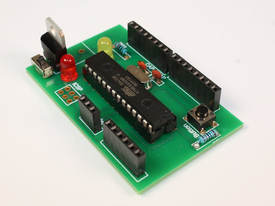
We’d like to introduce you to the Explorer Uno. Our first template, based on the board that started it all, the Arduino Uno. With the Explorer Uno, all you need is a breadboard, an Arduino Uno project and Patchr to make your idea a reality. We’ve used this template in everything from cosplay to IoT to #badgelife and art installations — anything that wasn’t possible with a bulky Arduino. We hope you use the Explorer Uno to start down the path to discovering the PCB projects that make you most excited.
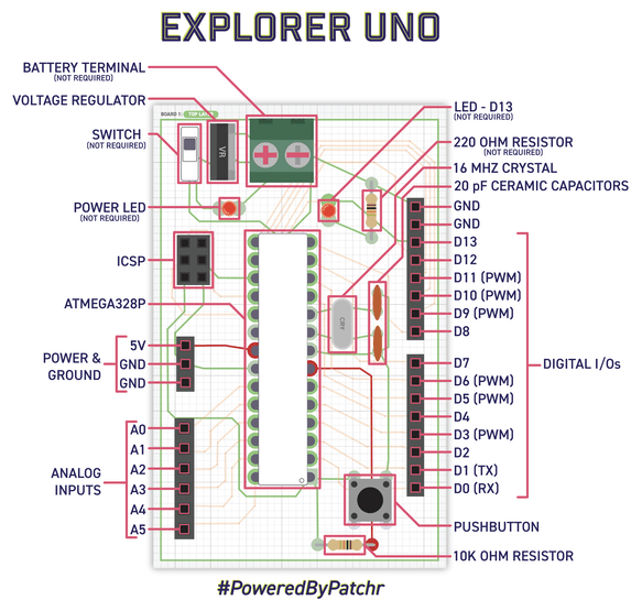
The Explorer Uno is perfect in that it has all the GPIOs you have come to love with the Arduino Uno with the ability to connect directly to them and delete the pins you don’t use. We’ve put together a diagram for you that shows which components are vital and which ones you can remove.
Check it out — all we need to do is log in to Patchr, select the “Explorer Uno” template next to the create new project button, annnnnnnnnd… Bada bing, bada boom! It’s ready to go. You can change the board footprint, add components, or just export as is.
We've included a BOM with the correct components linked below or you can use the component section above to buy items individually.
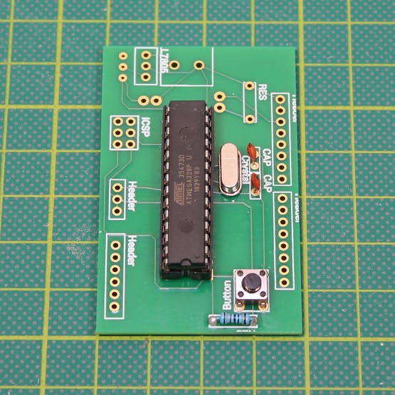
Let's start with the core of the Explorer Uno, the ATmega328, the brains. This is what tells your project what to do and when to do it. Tip: Make sure that the indent on the top of this chip is facing down. You can also use a 28 pin IC socket to make it a bit easier to program and flip in case the ATmega328 is upside down. Button & Resistor - This helps reset your project once the software has been uploaded into the ATmega328. Clock & Capacitors - Time! This 16 MHz beauty counts the seconds so you don’t have to. Switch - On and off, on and off, on and off. We added a red LED so you can tell when the Explorer is on.... or off. LED Pin 13 + Resistor - This is your proof of life light when uploading software or running simple sketches look at this light to be sure everything is running smoothly. Voltage Regulator - This bad boy helps make sure the only thing you are blowing is people’s minds… and not the components on your PCB. We like to use a 9V battery to power our projects, and this will drop it down to 5V to keep everything running smooth. Power - There are so many options here. You can use anything that supplies 5V or more. Just connect the positive and negative leads to the through holes as shown in the diagram below: