
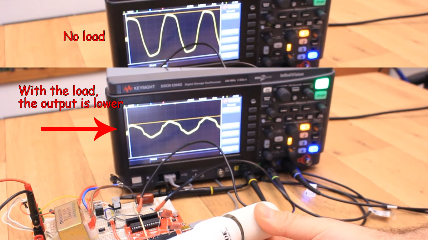
Ok, now this was nos implemented with code. But, if you look at my video on this tutorial, you will see that when we add a load at the output, the wave amplitude and shape will change. So, a feedback would detect that and the cirduit will increase or decrease the input DC vale so the AC output value will stay the same. The idea goes like this. We rectify the output and using a voltage divider we lower the value so we could read that with the Arduino.
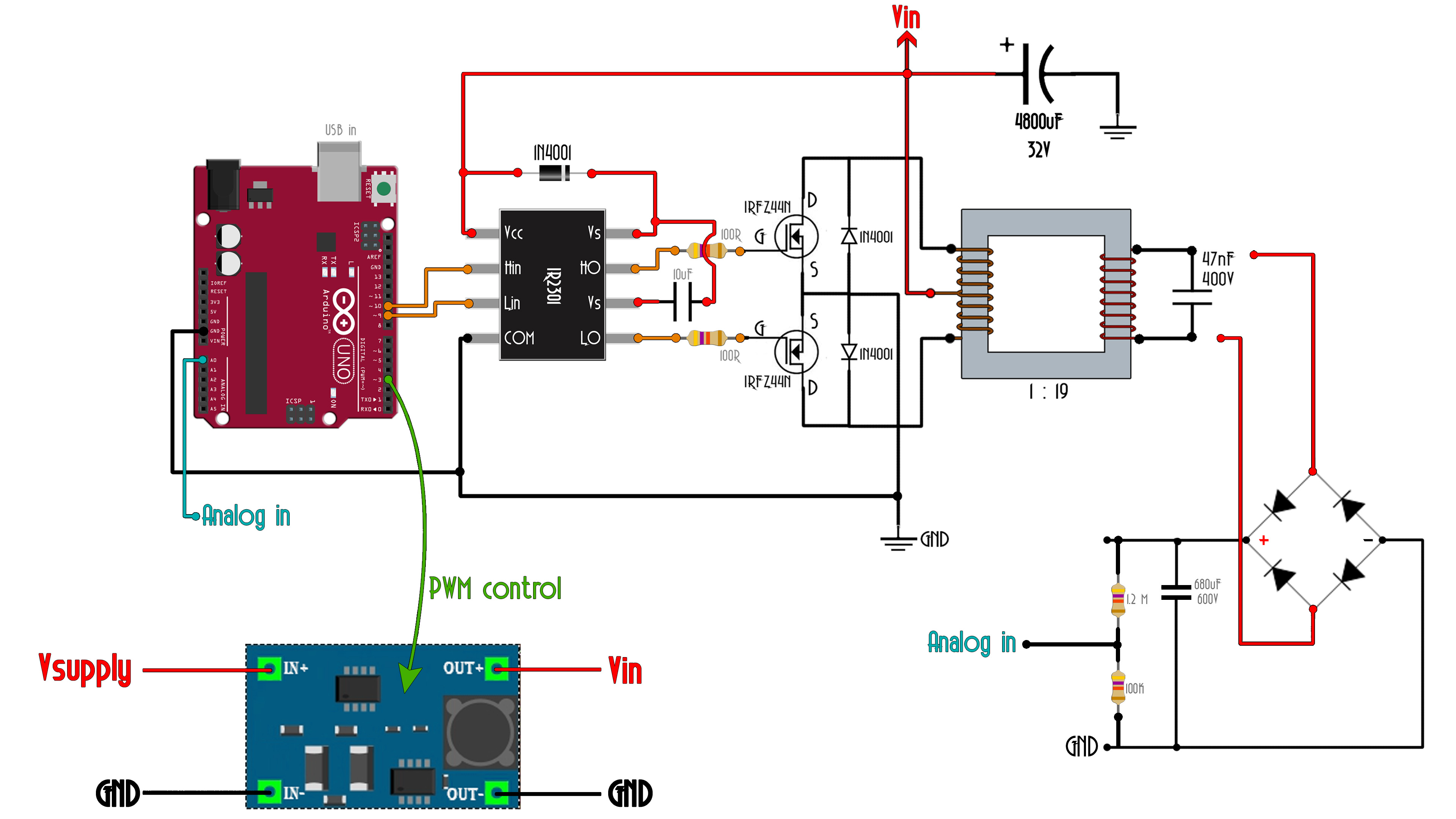
Once we read the output value, if the value is below let's say 230V AC, well, we increae the DC input till we have 230V at the output. If is hiugher than that, we lower the input DC value. TO do that we could use a boost/buck circuit as we have seen in a previous video. Make this with the Arduino is very difficult since we need to react very fast and the Arduino is not the best way to do that.
And that's it for this tutorial. See more in the video below. I hope you liked this project. Also see my tutorial on inverters here on this link. Consider supporting my projects on my Patreon page or PayPal on my DONATE page. Thank you very much.


