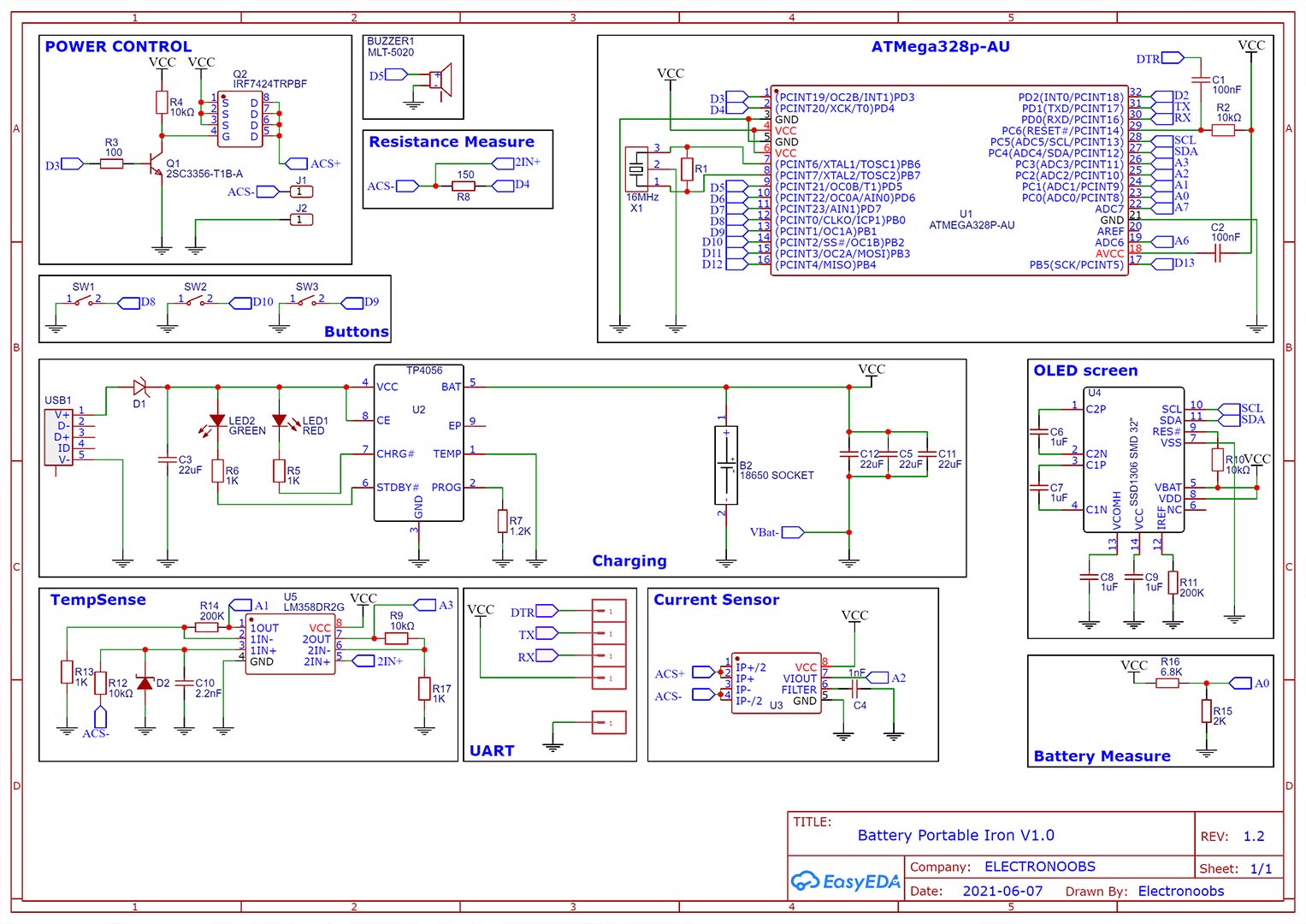
The schematic is this one below. To control the power output, we use the MOSFET. This could work up to 6 amps at 20V. Is not really necessary since the supply voltage is the same as the gate voltage, but I’ve also use a small BJT as a gate driver. Then we have the charging module connected to the USB connector and on the other side to the battery and this will give us VCC value. As you have seen on the screen, we also measure the resistance of the iron tip. To do that, we use a voltage divider between the tip resistance and the R8 resistor and since the output voltage is so low, we use an operational amplifier to amplify that voltage and read it with the Arduino ADC. Below we have the current sensor, the ACS712. The PCB also has the UART pads so we could program the microcontroller and also the pads connections for the small OLED display.