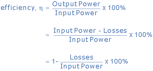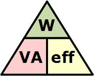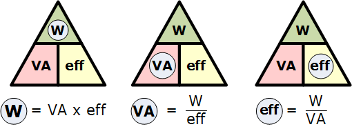

A transformer does not require any moving parts to transfer energy. This means that there are no friction or windage losses associated with other electrical machines. However, transformers do suffer from other types of losses called “copper losses” and “iron losses” but generally these are quite small. Copper losses, also known as I2R loss is the electrical power which is lost in heat as a result of circulating the currents around the transformers copper windings, hence the name. Copper losses represents the greatest loss in the operation of a transformer. The actual watts of power lost can be determined (in each winding) by squaring the amperes and multiplying by the resistance in ohms of the winding (I2R). Iron losses, also known as hysteresis is the lagging of the magnetic molecules within the core, in response to the alternating magnetic flux. This lagging (or out-of-phase) condition is due to the fact that it requires power to reverse magnetic molecules; they do not reverse until the flux has attained sufficient force to reverse them. Their reversal results in friction, and friction produces heat in the core which is a form of power loss. Hysteresis within the transformer can be reduced by making the core from special steel alloys. The intensity of power loss in a transformer determines its efficiency. The efficiency of a transformer is reflected in power (wattage) loss between the primary (input) and secondary (output) windings. Then the resulting efficiency of a transformer is equal to the ratio of the power output of the secondary winding, PS to the power input of the primary winding, PP and is therefore high. An ideal transformer is 100% efficient because it delivers all the energy it receives. Real transformers on the other hand are not 100% efficient and at full load, the efficiency of a transformer is between 94% to 96% which is quiet good. For a transformer operating with a constant voltage and frequency with a very high capacity, the efficiency may be as high as 98%. The efficiency, η of a transformer is given as:
Transformer Efficiency


Then to summarise this transformer basics tutorial. A Transformer changes the voltage level (or current level) on its input winding to another value on its output winding using a magnetic field. A transformer consists of two electrically isolated coils and operates on Faraday’s principal of “mutual induction”, in which an EMF is induced in the transformers secondary coil by the magnetic flux generated by the voltages and currents flowing in the primary coil winding.
Both the primary and secondary coil windings are wrapped around a common soft iron core made of individual laminations to reduce eddy current and power losses. The primary winding of the transformer is connected to the AC power source which must be sinusoidal in nature, while the secondary winding supplies electrical power to the load. Having said that, a transformer could be used in reverse with the supply connected to the secondary winding provided the voltage and current ratings are observed.
We can represent the transformer in block diagram form as follows:

The ratio of the transformers primary and secondary windings with respect to each other produces either a step-up voltage transformer or a step-down voltage transformer with the ratio between the number of primary turns to the number of secondary turns being called the “turns ratio” or “transformer ratio”.
If this ratio is less than unity, n < 1 then NS is greater than NP and the transformer is classed as a step-up transformer. If this ratio is greater than unity, n > 1, that is NP is greater than NS, the transformer is classed as a step-down transformer. Note that single phase step-down transformer can also be used as a step-up transformer simply by reversing its connections and making the low voltage winding its primary, and vice versa as long as the transformer is operated within its original VA design rating.
If the turns ratio is equal to unity, that is n = 1, then both the primary and secondary have the same number of coil turns so therefore the voltages and currents will be the same for both the primary and secondary windings.
This type of 1:1 transformer is classed as an isolation transformer as both the primary and secondary windings of the transformer have the same number of volts per turn. The efficiency of a transformer is the ratio of the power it delivers to the load to the power it absorbs from the supply. In an ideal transformer there are no losses so no loss of power then PIN = POUT.
In the next tutorial to do with Transformer Basics, we will look at the physical Construction of a Transformer and see the different magnetic core types and laminations used to support the primary and secondary windings.