Full theory from electronics-tutorials.ws. One of the main reasons that we use alternating AC voltages and currents in our homes and workplace’s is that AC supplies can be easily generated at a convenient voltage, transformed (hence the name transformer) into much higher voltages and then distributed around the country using a national grid of pylons and cables over very long distances.
The reason for transforming the voltage to a much higher level is that higher distribution voltages implies lower currents for the same power and therefore lower I2*R losses along the networked grid of cables. These higher AC transmission voltages and currents can then be reduced to a much lower, safer and usable voltage level where it can be used to supply electrical equipment in our homes and workplaces, and all this is possible thanks to the basic Voltage Transformer.
The Voltage Transformer can be thought of as an electrical component rather than an electronic component. A transformer basically is very simple static (or stationary) electro-magnetic passive electrical device that works on the principle of Faraday’s law of induction by converting electrical energy from one value to another.
The transformer does this by linking together two or more electrical circuits using a common oscillating magnetic circuit which is produced by the transformer itself. A transformer operates on the principals of “electromagnetic induction”, in the form of Mutual Induction.
Mutual induction is the process by which a coil of wire magnetically induces a voltage into another coil located in close proximity to it. Then we can say that transformers work in the “magnetic domain”, and transformers get their name from the fact that they “transform” one voltage or current level into another.
Transformers are capable of either increasing or decreasing the voltage and current levels of their supply, without modifying its frequency, or the amount of electrical power being transferred from one winding to another via the magnetic circuit.
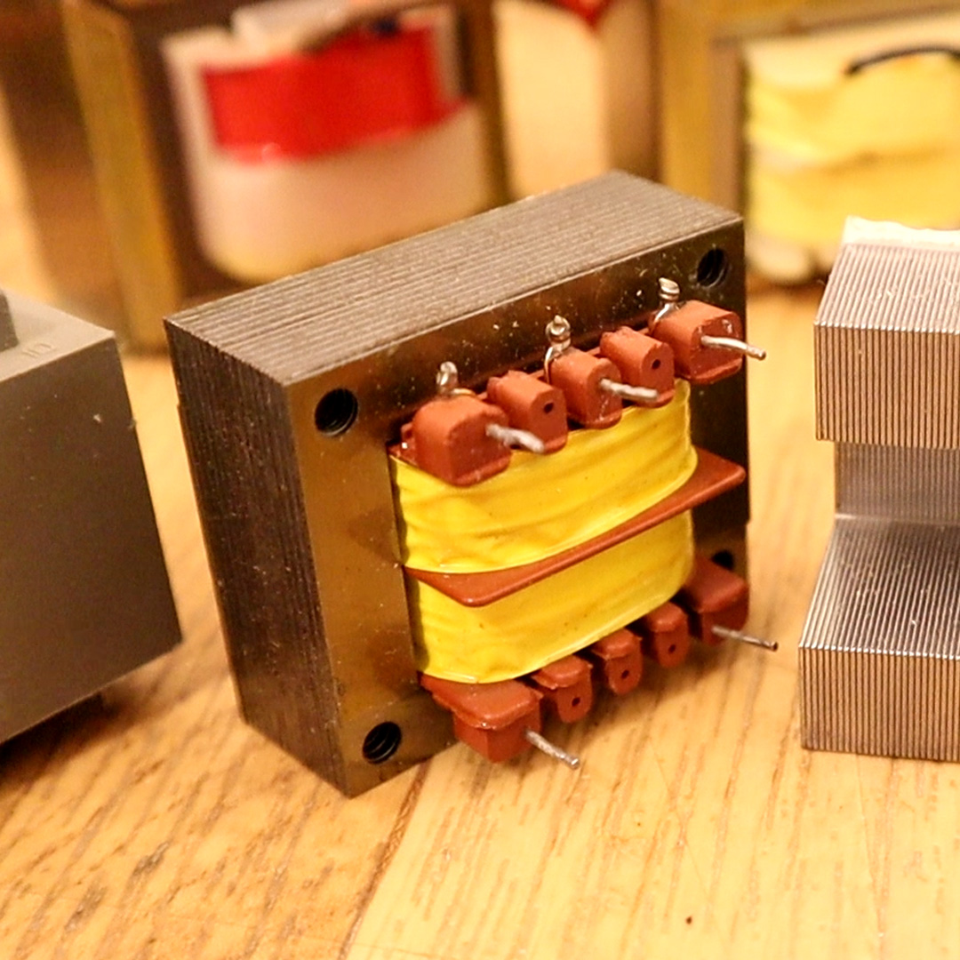
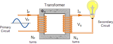
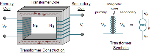
A single phase voltage transformer basically consists of two electrical coils of wire, one called the “Primary Winding” and another called the “Secondary Winding”. For this tutorial we will define the “primary” side of the transformer as the side that usually takes power, and the “secondary” as the side that usually delivers power. In a single-phase voltage transformer the primary is usually the side with the higher voltage.
These two coils are not in electrical contact with each other but are instead wrapped together around a common closed magnetic iron circuit called the “core”. This soft iron core is not solid but made up of individual laminations connected together to help reduce the core’s losses.
The two coil windings are electrically isolated from each other but are magnetically linked through the common core allowing electrical power to be transferred from one coil to the other. When an electric current passed through the primary winding, a magnetic field is developed which induces a voltage into the secondary winding as shown.
In other words, for a transformer there is no direct electrical connection between the two coil windings, thereby giving it the name also of an Isolation Transformer. Generally, the primary winding of a transformer is connected to the input voltage supply and converts or transforms the electrical power into a magnetic field. While the job of the secondary winding is to convert this alternating magnetic field into electrical power producing the required output voltage as shown.
Where:
- VP – is the Primary Voltage
- VS – is the Secondary Voltage
- NP – is the Number of Primary Windings
- NS – is the Number of Secondary Windings
- Φ (phi) – is the Flux Linkage
Notice that the two coil windings are not electrically connected but are only linked magnetically. A single-phase transformer can operate to either increase or decrease the voltage applied to the primary winding. When a transformer is used to “increase” the voltage on its secondary winding with respect to the primary, it is called a Step-up transformer. When it is used to “decrease” the voltage on the secondary winding with respect to the primary it is called a Step-down transformer.
However, a third condition exists in which a transformer produces the same voltage on its secondary as is applied to its primary winding. In other words, its output is identical with respect to voltage, current and power transferred. This type of transformer is called an “Impedance Transformer” and is mainly used for impedance matching or the isolation of adjoining electrical circuits.
The difference in voltage between the primary and the secondary windings is achieved by changing the number of coil turns in the primary winding ( NP ) compared to the number of coil turns on the secondary winding ( NS ).
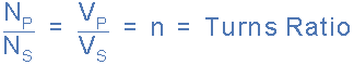
As the transformer is basically a linear device, a ratio now exists between the number of turns of the primary coil divided by the number of turns of the secondary coil. This ratio, called the ratio of transformation, more commonly known as a transformers “turns ratio”, ( TR ). This turns ratio value dictates the operation of the transformer and the corresponding voltage available on the secondary winding.
It is necessary to know the ratio of the number of turns of wire on the primary winding compared to the secondary winding. The turns ratio, which has no units, compares the two windings in order and is written with a colon, such as 3:1 (3-to-1). This means in this example, that if there are 3 volts on the primary winding there will be 1 volt on the secondary winding, 3 volts-to-1 volt. Then we can see that if the ratio between the number of turns changes the resulting voltages must also change by the same ratio, and this is true.
Transformers are all about “ratios”. The ratio of the primary to the secondary, the ratio of the input to the output, and the turns ratio of any given transformer will be the same as its voltage ratio. In other words for a transformer: “turns ratio = voltage ratio”. The actual number of turns of wire on any winding is generally not important, just the turns ratio and this relationship is given as:
Assuming an ideal transformer and the phase angles: ΦP ≡ ΦS Note that the order of the numbers when expressing a transformers turns ratio value is very important as the turns ratio 3:1 expresses a very different transformer relationship and output voltage than one in which the turns ratio is given as: 1:3.
Transformer Basics Example No1
A voltage transformer has 1500 turns of wire on its primary coil and 500 turns of wire for its secondary coil. What will be the turns ratio (TR) of the transformer.
Transformer Basics Example No2
If 240 volts rms is applied to the primary winding of the same transformer above, what will be the resulting secondary no load voltage.
We have seen that the number of coil turns on the secondary winding compared to the primary winding, the turns ratio, affects the amount of voltage available from the secondary coil. But if the two windings are electrically isolated from each other, how is this secondary voltage produced? We have said previously that a transformer basically consists of two coils wound around a common soft iron core. When an alternating voltage ( VP ) is applied to the primary coil, current flows through the coil which in turn sets up a magnetic field around itself, called mutual inductance, by this current flow according to Faraday’s Law of electromagnetic induction. The strength of the magnetic field builds up as the current flow rises from zero to its maximum value which is given as dΦ/dt.
As the magnetic lines of force setup by this electromagnet expand outward from the coil the soft iron core forms a path for and concentrates the magnetic flux. This magnetic flux links the turns of both windings as it increases and decreases in opposite directions under the influence of the AC supply.
However, the strength of the magnetic field induced into the soft iron core depends upon the amount of current and the number of turns in the winding. When current is reduced, the magnetic field strength reduces.
When the magnetic lines of flux flow around the core, they pass through the turns of the secondary winding, causing a voltage to be induced into the secondary coil. The amount of voltage induced will be determined by: N*dΦ/dt (Faraday’s Law), where N is the number of coil turns. Also this induced voltage has the same frequency as the primary winding voltage.
Then we can see that the same voltage is induced in each coil turn of both windings because the same magnetic flux links the turns of both the windings together. As a result, the total induced voltage in each winding is directly proportional to the number of turns in that winding. However, the peak amplitude of the output voltage available on the secondary winding will be reduced if the magnetic losses of the core are high.
If we want the primary coil to produce a stronger magnetic field to overcome the cores magnetic losses, we can either send a larger current through the coil, or keep the same current flowing, and instead increase the number of coil turns ( NP ) of the winding. The product of amperes times turns is called the “ampere-turns”, which determines the magnetising force of the coil.
So assuming we have a transformer with a single turn in the primary, and only one turn in the secondary. If one volt is applied to the one turn of the primary coil, assuming no losses, enough current must flow and enough magnetic flux generated to induce one volt in the single turn of the secondary. That is, each winding supports the same number of volts per turn.
As the magnetic flux varies sinusoidally, Φ = Φmax sinωt, then the basic relationship between induced emf, ( E ) in a coil winding of N turns is given by:
Where:
- ƒ – is the flux frequency in Hertz, = ω/2π
- Ν – is the number of coil windings.
- Φ – is the amount of flux in webers
This is known as the Transformer EMF Equation. For the primary winding emf, N will be the number of primary turns, ( NP ) and for the secondary winding emf, N will be the number of secondary turns, ( NS ).
Also please note that as transformers require an alternating magnetic flux to operate correctly, transformers cannot therefore be used to transform or supply DC voltages or currents, since the magnetic field must be changing to induce a voltage in the secondary winding. In other words, transformers DO NOT operate on steady state DC voltages, only alternating or pulsating voltages.
If a transformers primary winding was connected to a DC supply, the inductive reactance of the winding would be zero as DC has no frequency, so the effective impedance of the winding will therefore be very low and equal only to the resistance of the copper used. Thus the winding will draw a very high current from the DC supply causing it to overheat and eventually burn out, because as we know I = V/R.
Transformer Basics Example No3
A single phase transformer has 480 turns on the primary winding and 90 turns on the secondary winding. The maximum value of the magnetic flux density is 1.1T when 2200 volts, 50Hz is applied to the transformer primary winding. Calculate:
a). The maximum flux in the core.