If you ever opened a power supply of some sort, you might have seen a special component. That is a transformer but used in a FLYBACK configuration or sometimes called a coupled inductor. You will also notice that the transformer doesn’t have just one input and one output as common transformers do. It has a lot more pins and we will see why in this tutorial. I will show you how a FLYBACK DC to DC converter works. We have already seen the boost and the buck converters in some past tutorials, but we still have one more to see, and that’s the FLYBACK DC to DC converter. I will show you examples of how we could regulate DC voltage using a transformer, a simple circuit and the Arduino to generate the signal for the demonstration. I will also explain all the theory behind this converter so you will learn how it works and what to have in mind, and the most important, what advantages this FLYBACK converter has against the simple boots and buck converters.
Ok, so to understand how this works, let's start with a test. This component below is called a choke and is used in switching supplies to block higher-frequency while passing direct current. But we could use it today as a 1 to 1 transformer. Because, in the end, that’s what it is. We have two windings, one on each side, with the same amount of turns, and a ferromagnetic material passing through, and that creates a transformer. We could use this in our todays experiment as a FLYBACK transformer and create a DC to DC converter.
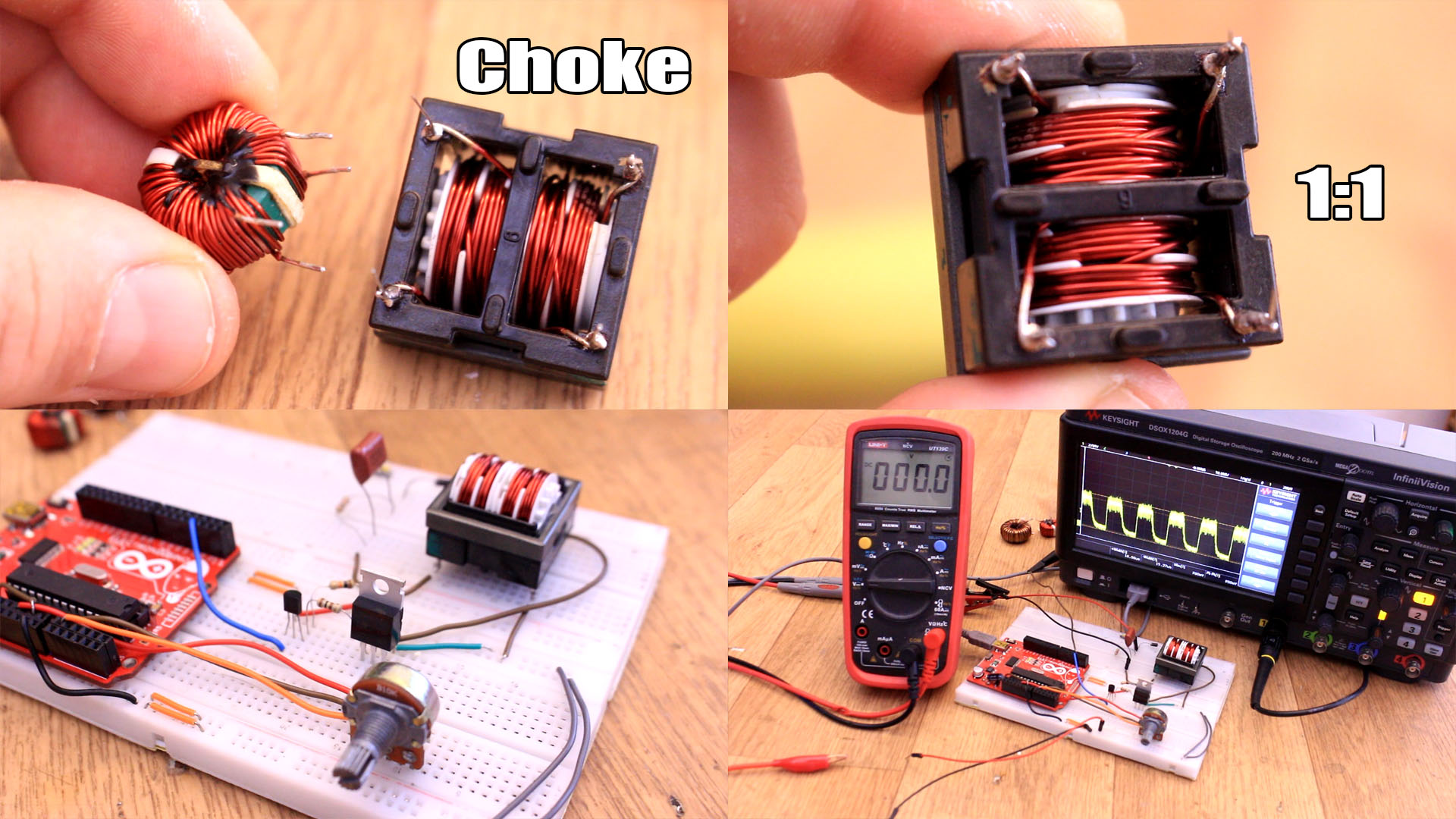
I place this component on my breadboard. I will use an Arduino to create a fast PWM pulse that will change its value with the potentiometer, as you can see now on the oscilloscope. We will se later how with this pulse we can change the output voltage of our circuit.
I apply this pulse to some transistors that will be connected to the primary winding of the FLYBACK transformer. At the secondary winding we have to place a diode, a capacitor and a small resistor as a load. Now, I supply 12V at the input of this simple circuit and look what happens. By changing the PWM signal, we can change the output voltage, just as with the buck or boost converters from the past tutorials. We can get a pretty-decent control of the output. I can easily set it to 5V for example using the potentiometer.
Instead of the potentiometer, we could add a simple feedback connected to the Arduino analog input, and set the voltage at a defined value, let’s say 5V. And the coupled inductor doesn’t have to be this big. A small one would do the job as well. So, is very simple to regulate DC voltage with this circuit, but not just that. We have a lot of other advantages by using this setup, so let’s start and see how the FLYBACK converter works.
Ok, below we can see the same circuit we had in the buck or boost tutorial with a coil and diode. But now, instead of that coil we use a transformer, for the first example, with a 1 to 1 ratio. So, how a 1 to 1 transformer could increase or decrease DC voltage. Well, we will see that when we add a diode at the output of the transformer, that will act as a coupled inductor.
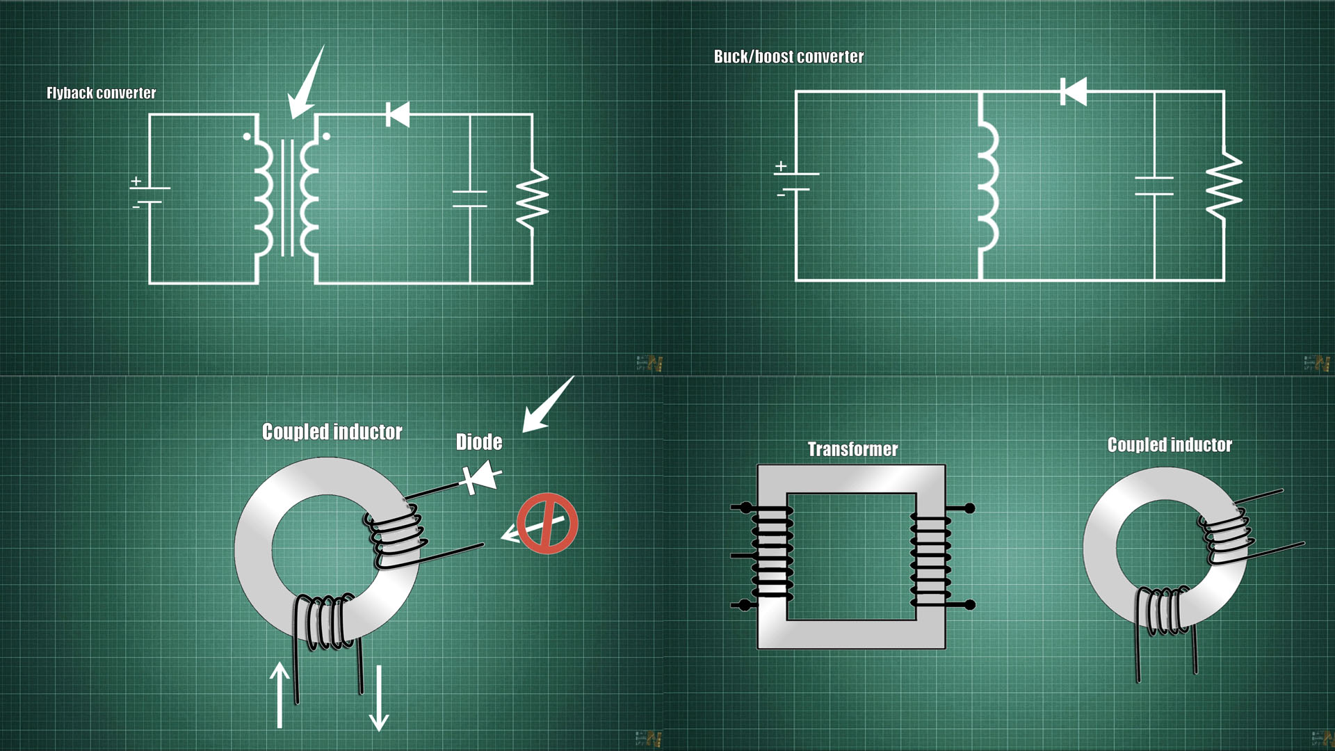
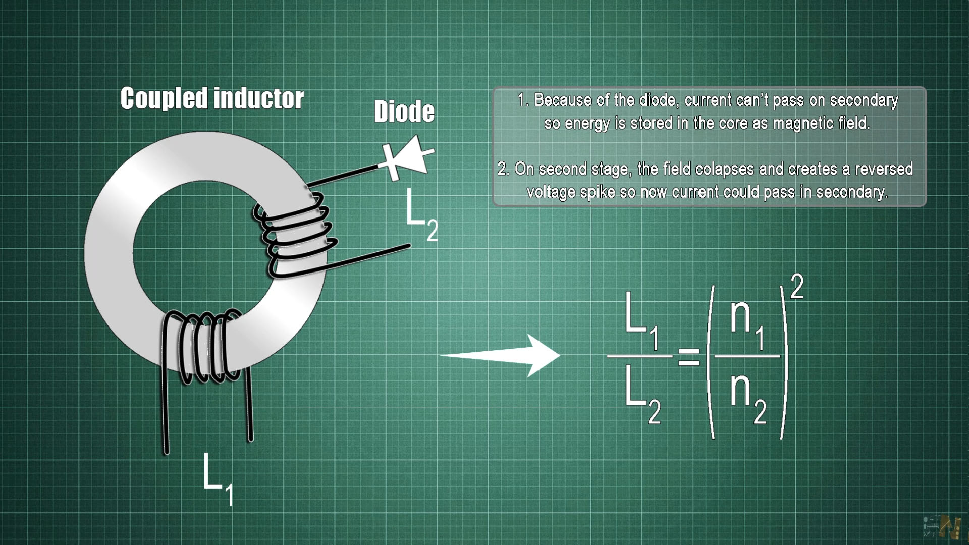
In a transformer, we push current through the first winding and another current will pass through the secondary winding and the load attached to that, that’s something basic. In a coupled inductor, we will see later, that because we have a diode at the secondary winding, when we push current trough the first winding, current won’t be able to pass trough the secondary winding. But that energy must go somewhere. Well, the energy will be stored in the core of the inductor as a magnetic field, just as we have seen in the boost/buck tutorial.
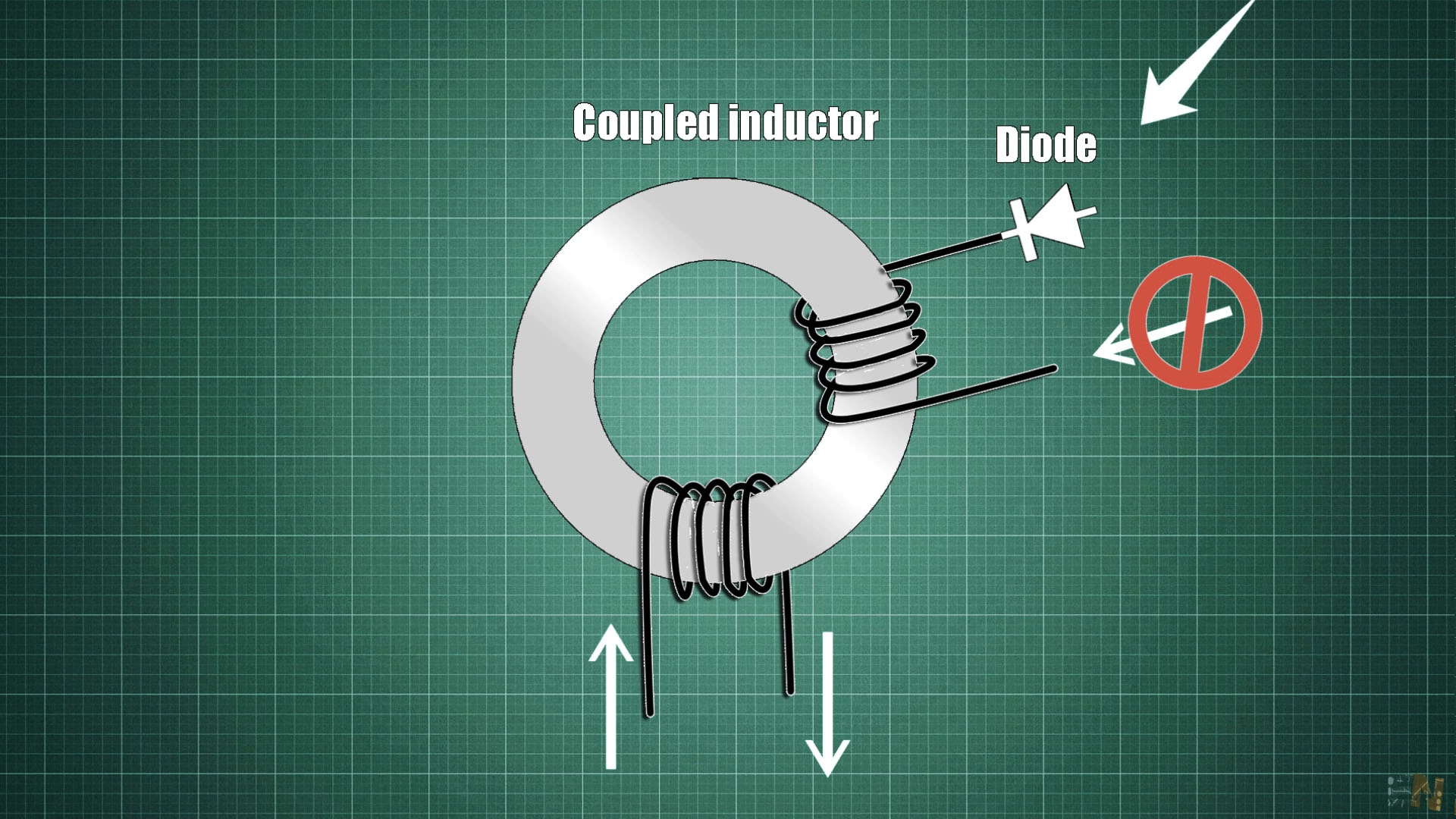
Then, in the second stage of the voltage conversion, when we cut the current from the primary, the magnetic field created will collapse and push current in the opposite way in the secondary winding. That’s why, in this configuration, our transformer acts as a coupled inductor, but if we look at the current and voltage values, the coupled inductor acts as a transformer, so we could have a gain and the inductance ratio is given by this formula where n is the amount of turns of each winding.
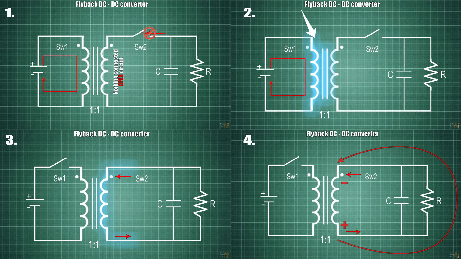
Ok, so let’s get into more details. This is our circuit now below. Here we have the coupled inductor with a 1 to 1 ratio and the primary is connected to the power supply trough a switch (SW1). The secondary also has a switch (SW2) in order to disconnect the load when we need to. Let’s say we close the first switch and open the second switch. The secondary will be in open circuit so no current could pass trough that coil. So, the energy will build up in the core of the coupled inductor.
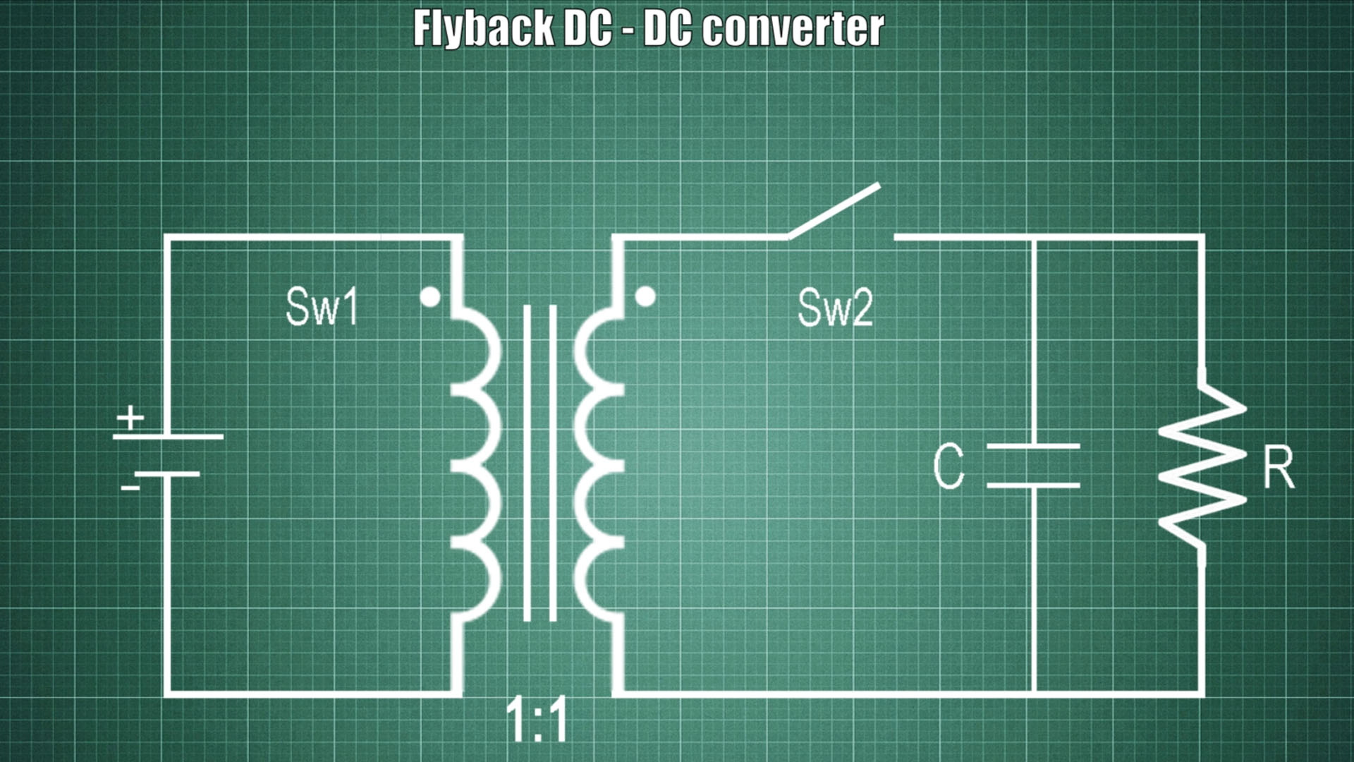
Then, in a very fast instant, we open switch 1 and close switch 2. The magnetic field that build up will collapse and current will now flow towards the dot of the secondary coil, so a voltage drop will be crated in this way, so we have reversed polarity. So, we can use this reversed polarity voltage in order to get rid of the second switch.