


I’m starting a new series of short videos/tutorials that will provide basic knowledge on electronic components. It is very important to know how each of the most commune components work in order to be able to use them on our projects. Today we will start with the first component of this video series, the operational amplifier or better known as Op amp. We will take a look over the basic configurations of this component, how to use it in different situations, and finally see some small real example with each of it.
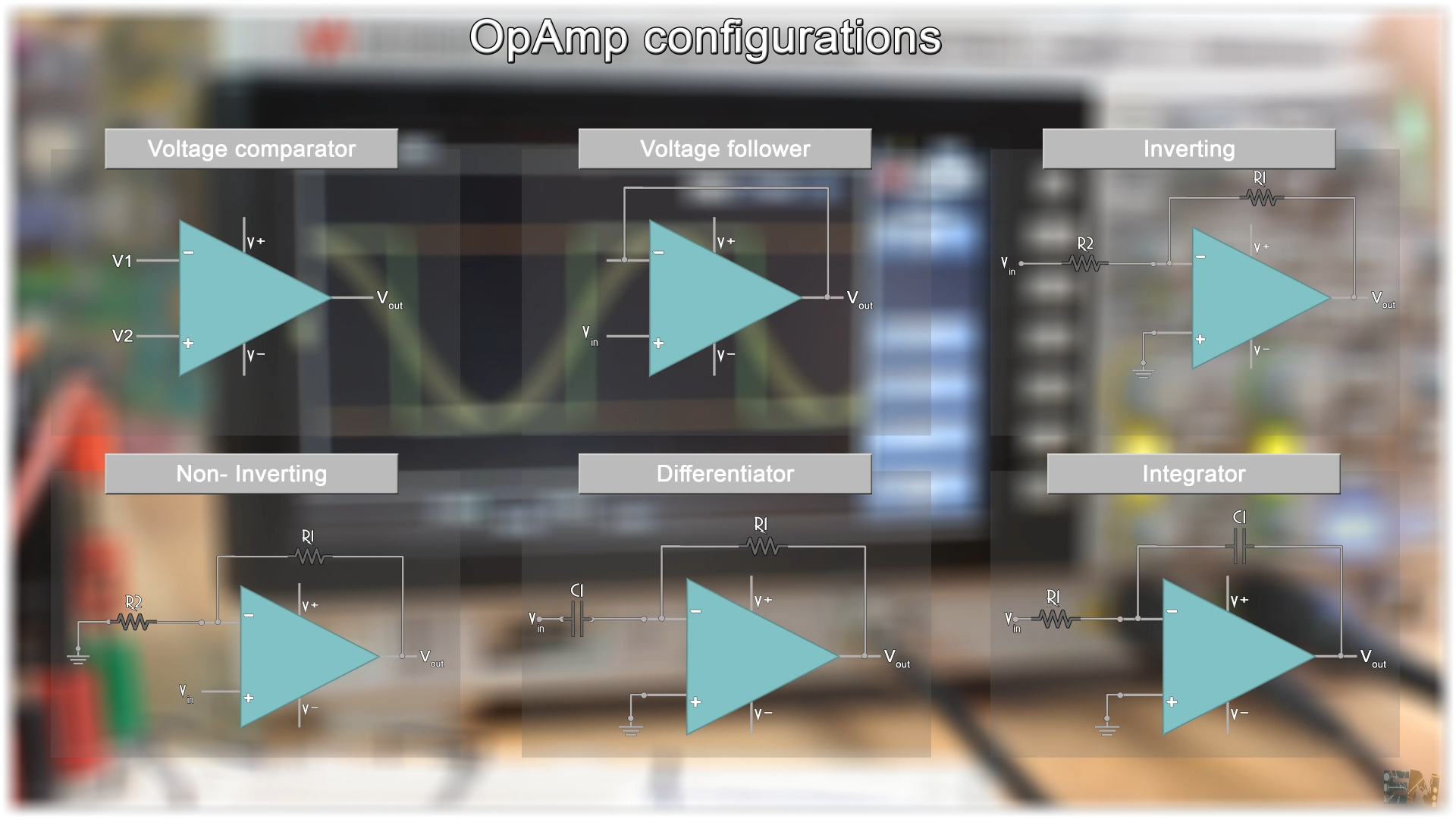
We will take a look over the comparator configuration, then the voltage follower and why we need a voltage follower. Next, we’ll talk about the inverting and non-inverting amplifying configuration and finally, a quick view over the integral and derivative configurations for cases where we want to achieve a ramp or spikes signals.
Well guys, let’s prepare the breadboard and see some basic examples, so let’s get started.

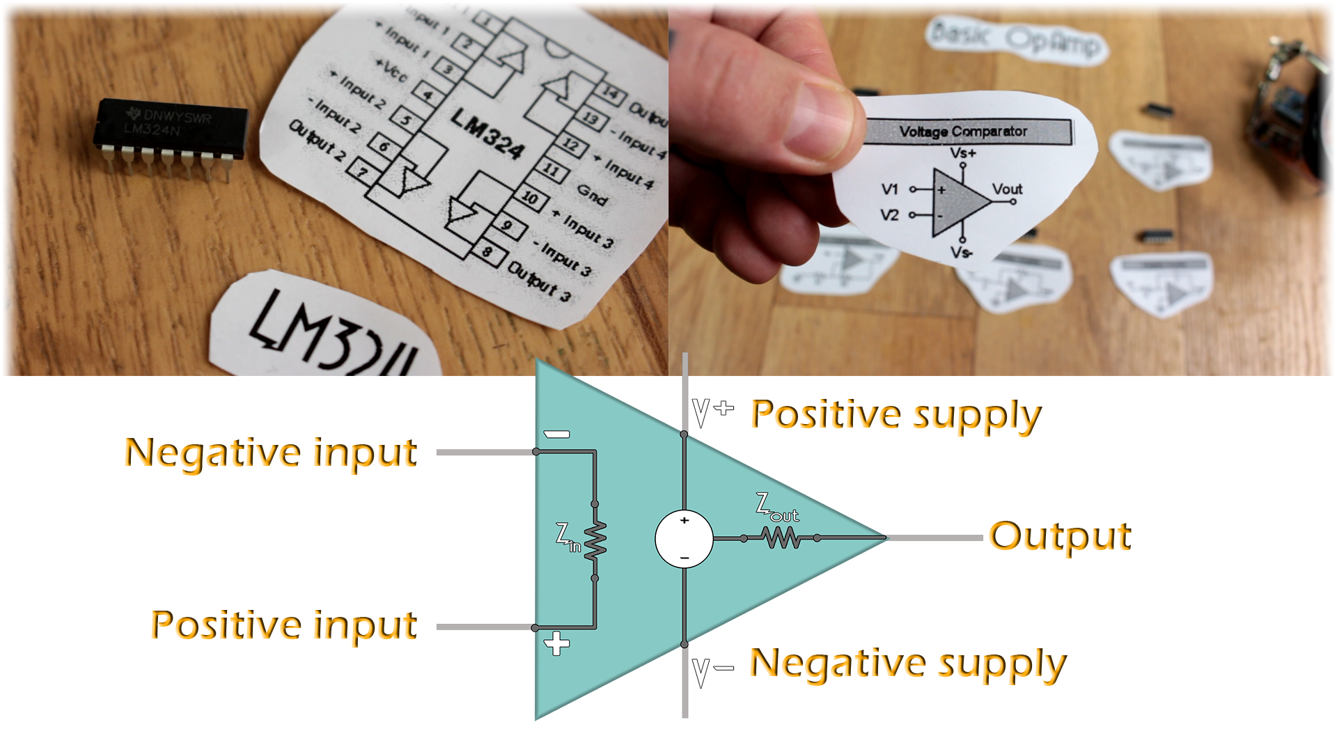
First of all, in the photo below you can see an operational amplifier IC, the LM324. That is its pinout and then you can see a basic OPAMP symbol, just a triangle with 5 pins. Those 5 pins are called positive and negative input, the output and the positive and negative supply of the amplifier.
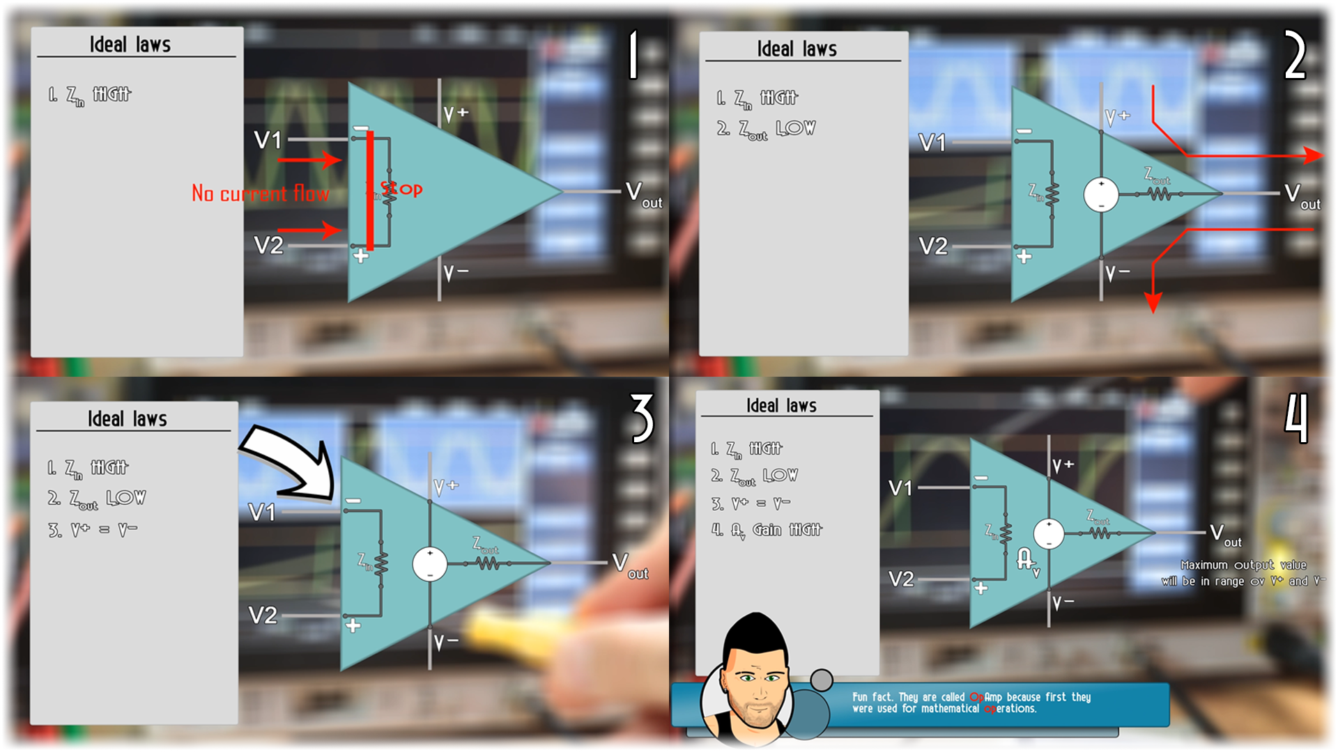
In the entire tutorial, we will talk abut the ideal amplifier, but in real life all its aspects won’t be perfect.
First ideal spec of the amplifier is that its input impedance is practically infinite, so no current could flow towards the amplifier on the input rails. Of course this is ideal. In real life that impedance is around 9M ohms so some current could flow towards the inside of the OpAmp on those rails. But as a ideal aspect it is very important to belive that the input is infinite.
Second spec is that the output impedance is low and current could flow inwards and outwards to the main supply. Of course this current value will be limited. Each IC has its own limit of output current. Later we will take a look over some limitations of the OpAmps.
Third ideal low, and a very important one, is that the voltage on the positive and negative input will always be the same, or at least the OPAMP will try that even it won’t succeed.
Finally, one more ideal low, the gain of an operational amplifier is very big or almost infinite. But of course, it won’t amplify the input signal by infinite. One obvious thing is that the output could have its maximum value, the supply of the OPAMP. It can’t be higher or lower than that. So even with gain infinite, the output will saturate at the input value.
Ok, now we know the basic ideal laws. Let's take a look over 6 different configurations with this OpAmp like the comparator, voltage follower, inverted amplification, non-inverted and finally integrator and differentiator.
Great, using these basic ideal laws, let’s talk about the comparator configuration. As its name tells us, this configuration will compare which of the inputs is higher. It works like this. The output of this configuration is the difference between the two inputs multiplied by the amplifier gain. Since the gain is infinite, whenever the positive input is lower than the negative, we will have a negative output, and when the positive is higher than the negative a positive output.
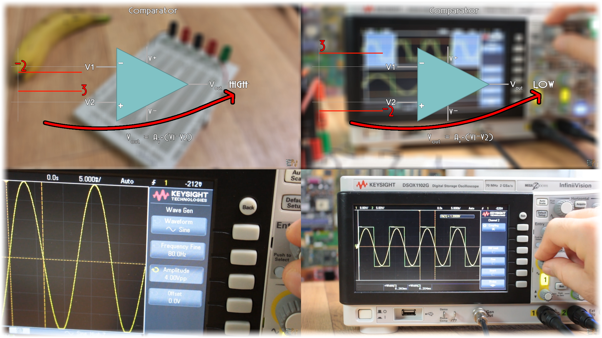
I place the LM324 on a breadboard and supply positive and negative 12 volts the supply pins. Next, I connected ground to the negative input of the amplifier and the output to my oscilloscope. At the positive input I’ll apply a sine wave with values from -2 to 2 volts. In the photo above, the yellow line is the input and the green it’s the output. As you can see, when the input value is above ground, the output is positive, and when the input is below ground, we have a negative output. That’s how this configuration works.
Now let’s see a limitation of the OPAMP. At the output I’ll place a potentiometer so I could vary the output load value. When the load is high, we have no problem. But when I start lowering itrs value, we can see that the output gets saturate. That’s because the OPAMP has a output current limit. Right in this moment if we look at the output voltage value and then measure the potentiometer value without changing its value, we could obtain that output current limit. Or maybe just check the datasheet of this amplifier.
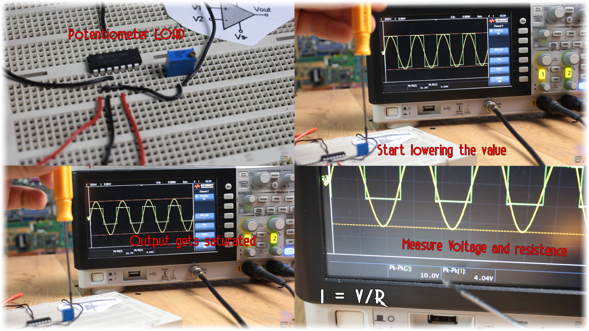
I've measured a peak to peak of 10 volts and a resistance of 158 ohms of the load. So the maximum current that the output could supply is around of 5V/159 equal to 31,6mA. Better check the datasheet for that.


