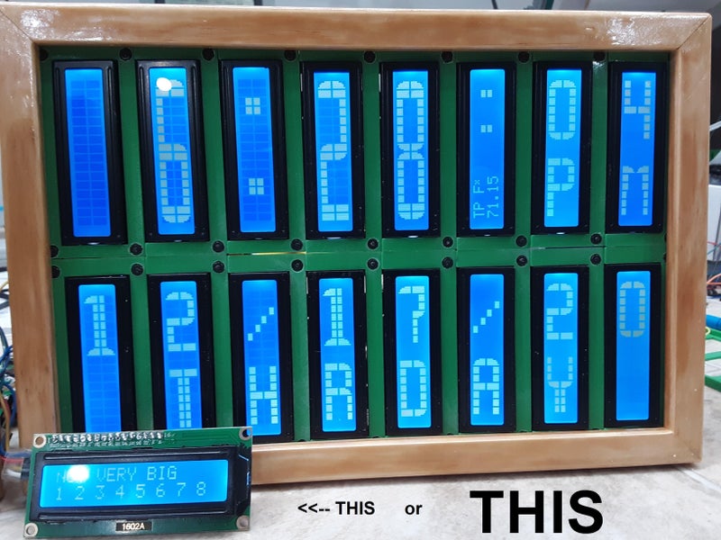
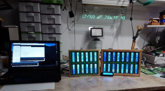
While the SSD1306 OLED has somewhat become the go-to display for up-to-date projects, the good old character displays with their Hitachi HD44780 controller don’t seem to be disappearing just yet either. And why would they, especially if you want to show just text, having a built-in font has certainly its perk compared to worrying about integrating your own characters — which you can still do on top as well. Or perhaps you can combine both worlds, which is what [oldmaninSC] did with his digital clock that takes an entire 16×2 LCD to show each single digit.
The whole clock uses 16 individual, upright rotated 16×2 LCDs that are arranged in two rows of eight LCDs each, turning the entire construct sort of into a giant 8×2 display itself. For some additional information such as the date, there’s also a smaller font available that uses only half the height, allowing up to four total rows of information. To communicate with each LCD via I2C, two TCA9548A I2C multiplexers are connected to an Arduino, along with an RTC to keep track of the time and date itself.
There are few choices if you need a display that can be seen from across the room, a big display. You can make one like my 'time squared' or 'leds on glass' but this takes about 40 hours of tedious work. So here is an EASY to make large display. The build has 4 basic wires, 5 volts, ground, SDA, SCL. Each character display cost about two to three dollars. So a 8x2 display is about $30. Not counting RTC, Arduino, 3d prints, enclosure.
The sketch is basic and easy to understand. Easy to modify for any alphanumeric display. The letters are 1/2 size with 1/2 size numbers and a set of full size numbers.
The drawback is you can only make a display of 64 char. The TCA9548 runs out of addresses (8). The Hitachi lcd is very SLOW and any larger display and the write time takes about a full second to fill the entire display. So if you wanted a wall size display it will be slow. There are many ways to cheat and use more than 64 lcds but I will not cover that in this post as this is an EASY to make display.
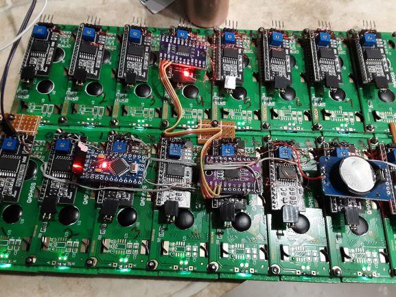
My first lcd array used nand gates and switched the lcd enable to the separate lcds. I then used the CD4051 chip that is made to switch data. It has an in and switched 8 line out. Just like an old fashion rotor switch. I have a pcb here. With this setup you can use an I2c and break the enable pin and connect iot to the input of the 4051 which switches the enable to the selected lcd. You can keep cascading the enable forever to lcds. But this limits the 4051 to only 7 switches and the 8th goes to the next 4051. this makes the banks = 7 not 8. I used all 8 and changed the address of another backpack in the second bank. this second backpack has a 4051 tied to the enable and does the same switching as in the first bank. Just has a second address on the SDA,SCL lines.
This setup requires ALL the 6 data lines of the lcd to be connected in parallel. The RW to ground. This takes much longer and I would recommend a plug in connector for each lcd. This setup is for only ONE backpack per bank instead of a backpack for each lcd.
Add a comment if you want more info about this setup. it is much harder and involved than the other.