In this tutorial I will show you how I've made my first version of this brushed DC motor speed controller. Please have in mind in the video I had some errors that I've fiexed in the final schematic. The controller has PWM control with 3 MOSFETs in parallel for more power and heat dissipation. It has a small hall effect sensor for current measure so we could also limit the current. It can read speed so that could also be limited and it has inputs for break and outputs for indicators.
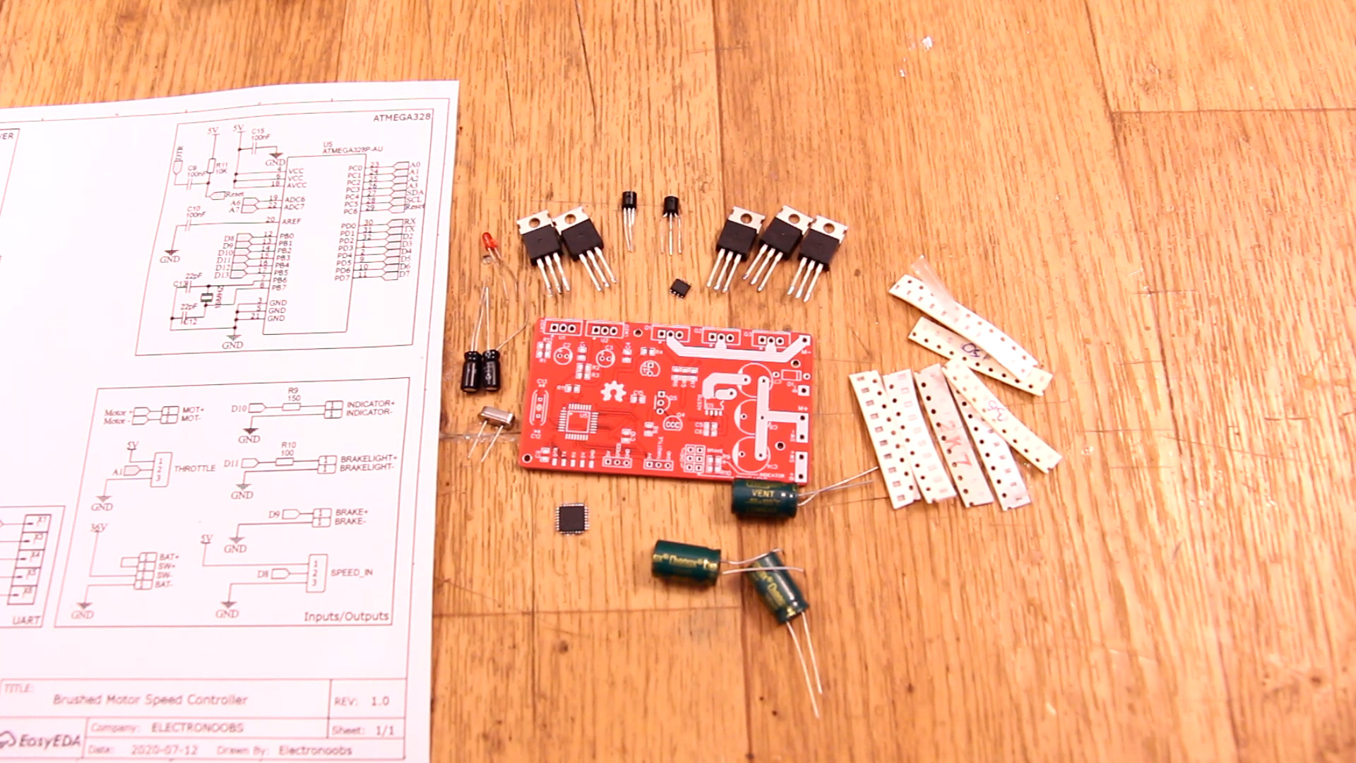
Below you have all the parts needed for the ESC PCB. You could also use a MSOFET driver instead of the BJT at the MOSFET gate. Aslo, for control and test, you will need wires, a potentiometer for throttle, the DC motor, some switches and a power supply. Check the list below and make the PCB.
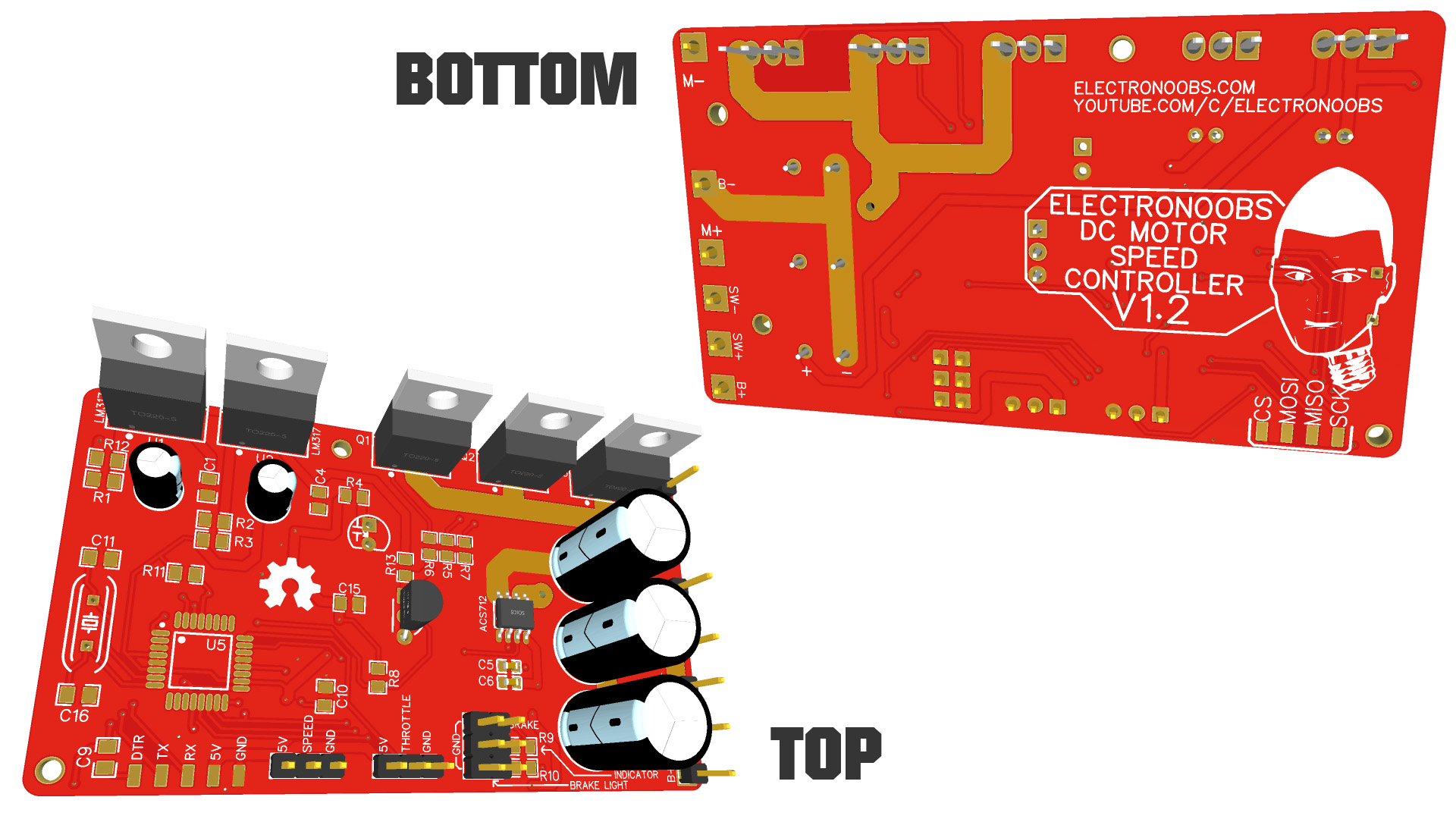
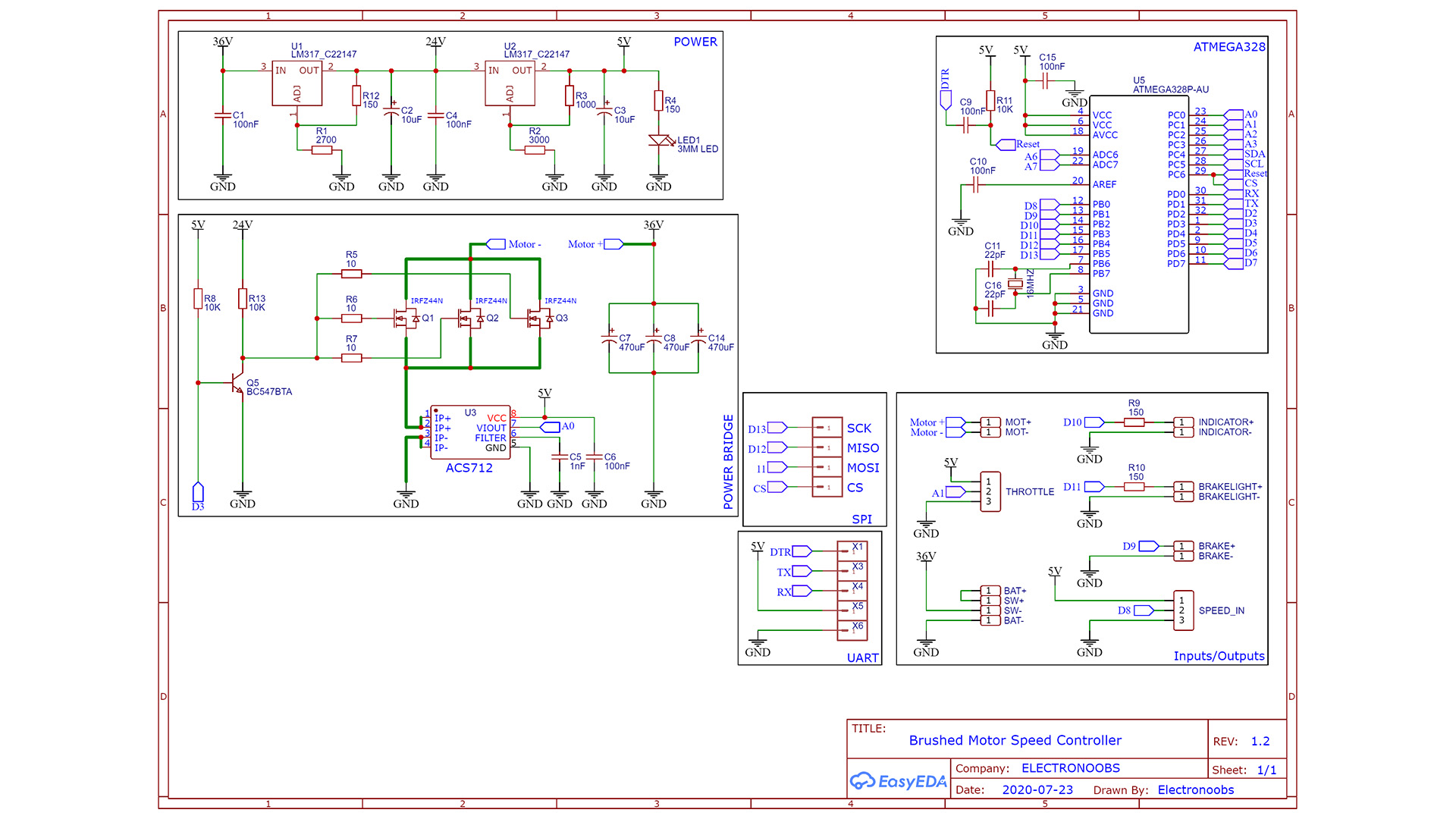
You have the scheamtic below. Remember that instead of the BC547 BJT you could add a MSOFET driver supplied at 24V and connected to the MOSFETs gate. The BJT has a pullup so it will be activated when the PCB starts, so the MOSFET gates are connected to GND, so those will be OFF. We don't want the MSOFETs to be ON for a short moment till the Arduino starts-up. The first part you will want to mount on the PCB is the "POWER" with the LM317 regulators. In this way, if the supplies fails and the output is higher than 5V, we won't burn the other components... Then add the ATmega328 basic configuration and then the rest of components.
You can make your own circuit on a breadboard for tests or maybe on a drilled prototyping PCB but if you want my PCB, you can download it from belwo for free. So go below, downlaod the .zip file with all the GERBERs and send it to a PCB manufacturer and get the boards. Then together with the schematic abobe and the part list, mount this project. Then upload the code and test it...
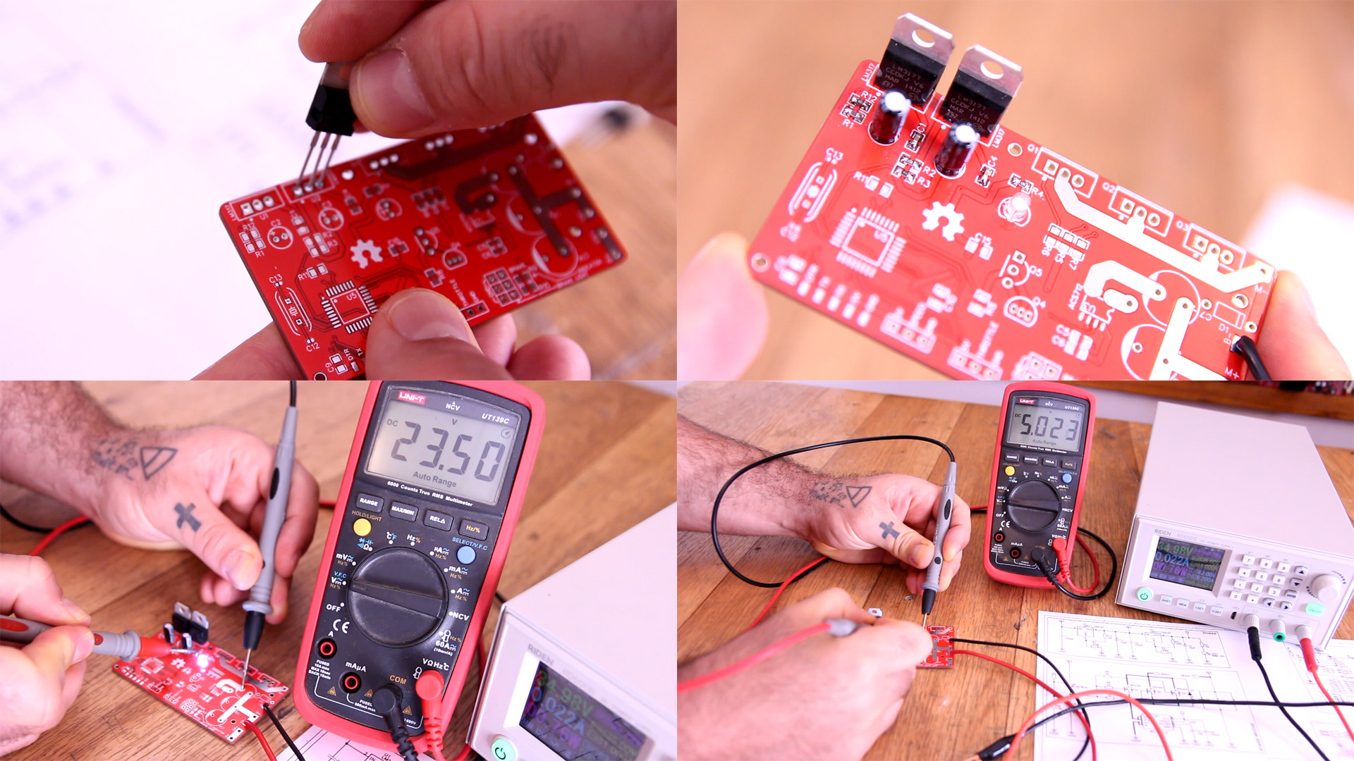
You must start mounting the PCB with the "Power" block from the schematic. In this way, if something fails and the voltage is more than 5V, we won't butn the rest of the ICs. So add the LM317, 10uF capacitors, small resistors and capacitors. Then solder wires at B- adn SW- pads and connect 35V at the input. With your multimeter, check the voltage on C5 and R4. The voltage should be around 23.5V on C4 and 5V on R1. The regulated voltage value is given by the used resistors, so make sure you use the same values as in the schematic.
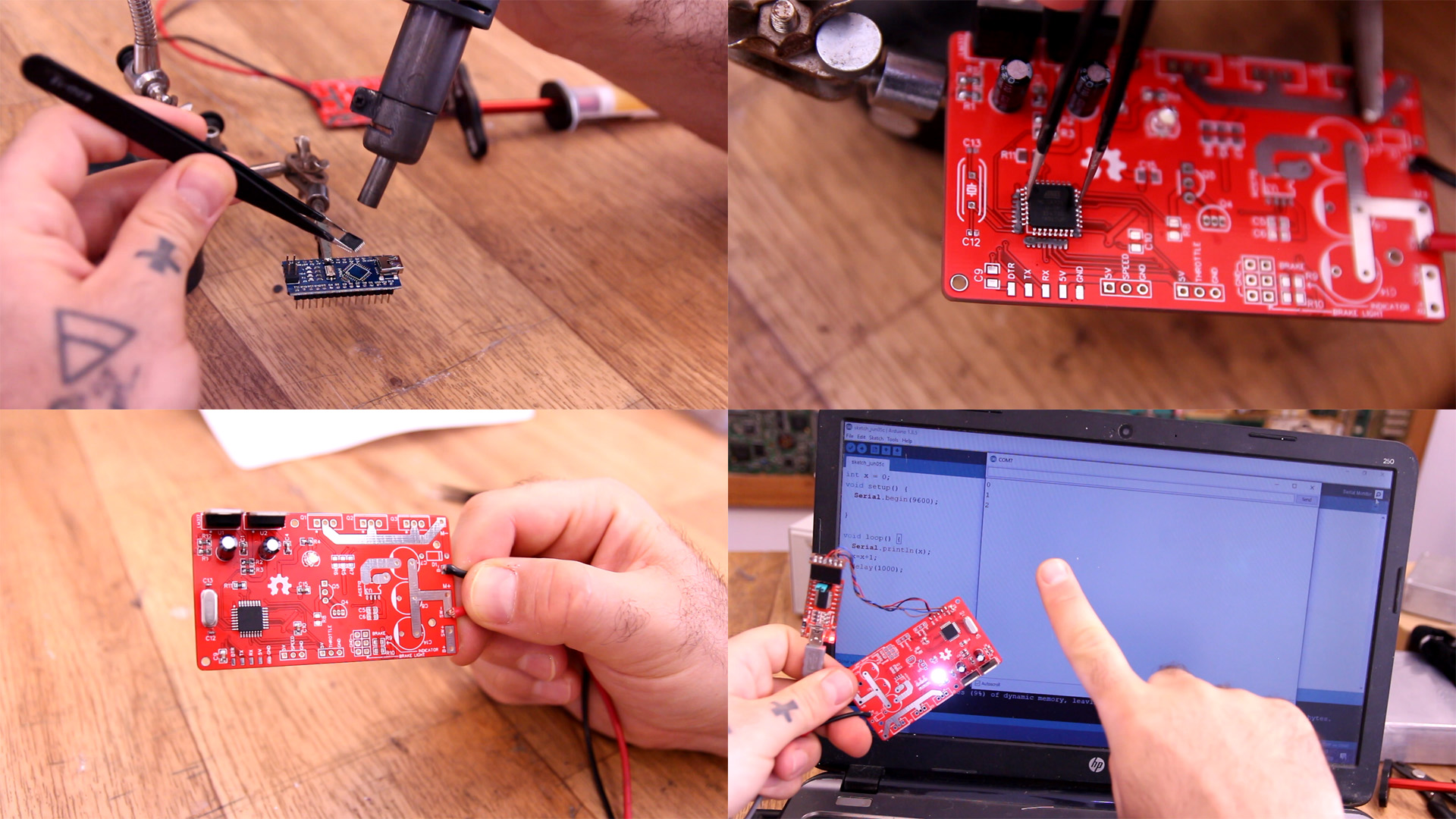
Now that we have 5V, we can solder the basic configuration of the ATmega328 chip, so solder all the components you have in that square on the schematic. In my case, to spare time, I've took the chip from an Arduino NANO. In this way, I make sure it has a bootloader and that is working. If you use a brand new chip, follow the next tutorial link and see how to burn the bootlaoder to taht chip. Ok, once you have the chip in place, the resistors, capacitors and crystal, you can test it. Connect an External FTDI programmer to the UART pins and test it. Uplaod a test sketch. If the code runs, than the chip is well soldered and works well. In my case I upload a counter and print that on the serial monitor so I can really see that it works...
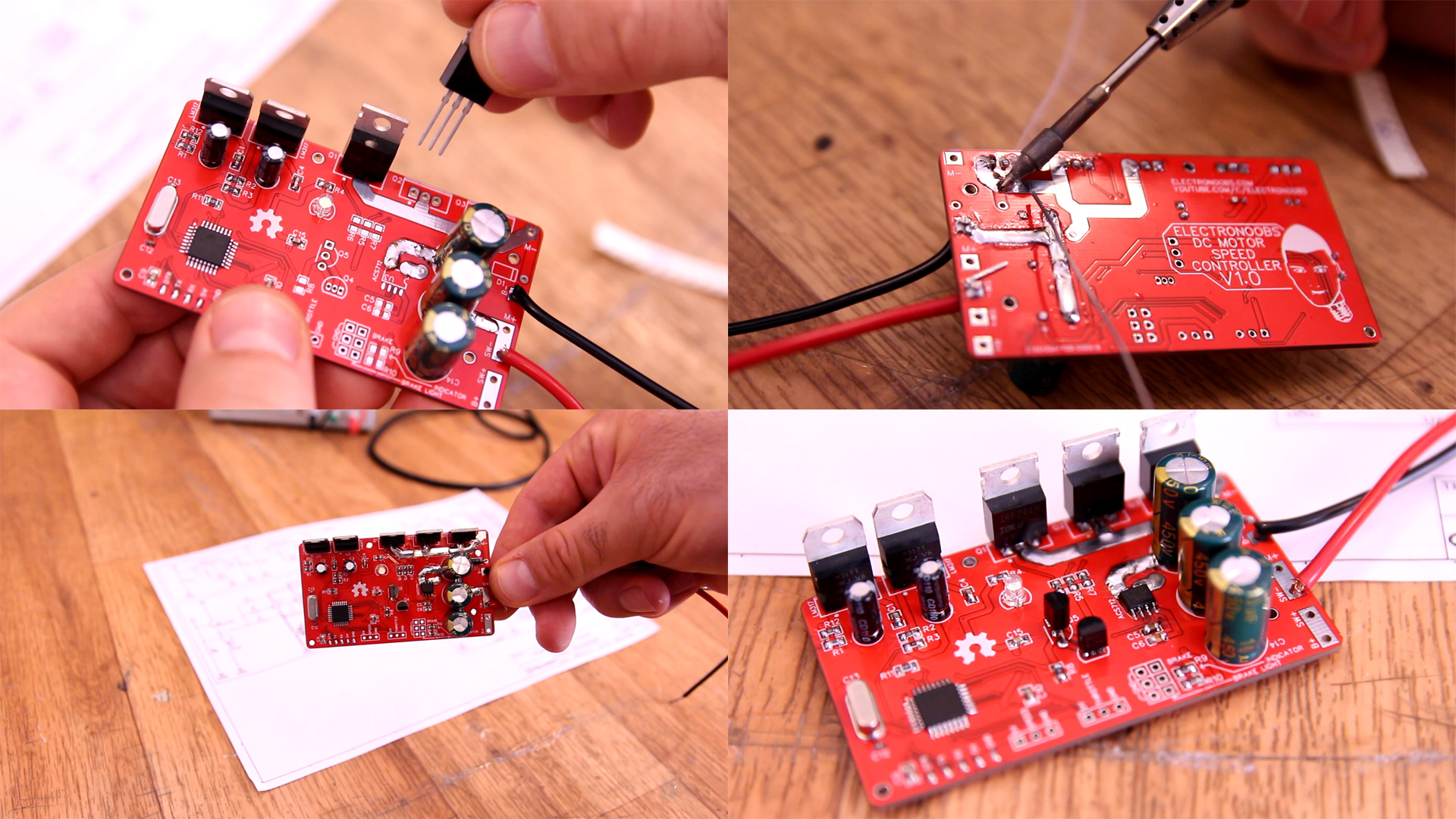
Now that the voltage and microcontroller are ok, we can solder all the rest. Add the MOSFETs, the 470uF capacitors, the BJT transistor and the rest of the resistors. Pay atention: in the photos I'm using the PCB with two BJT. You will have the one with just one. Then you can go anf fill the tracks with solder so they could withstant more current. That's why I've designed the PCB with the power tracks exposed. Add the current ACS712 IC, the cables and the rest. The PCB is ready for the code.
This version of the code has minimum speed detection but it doesn't have speed limit yet. It has only current limit with the feedback from the ACS712. The code starts with the BJT turned ON so we have GND at the MSOFETs gate so those would be OFF. Then, according to the throttle pot, we increase the PWM signal, which is inverter, 255 to 0 instead of 0 to 255, because the BJT acts as an inverter. We only activate the PWM signal if the speed is higher than a certain value and throttle is in the lowest position. We do this for saferty. We don't want the motor to start from 0, that will put it into humming mode and draw so much current it could burn the circuit. So, first, the user should pedal a bit and then accelerate. Read more in the code.
//Inputs/Outputs
int throttle_in = A1;       //Throttle potentiometer (0V - 5V)
int current_in = A0;        //From ACS712 IC
int speed_in = 8;           //From wheel hall sensor
int break_in = 9;           //From break switch
int breaklight = 11;        //To the break light LEDs
int indicator = 10;         //A small indicator LED (shows when contorller is ready)
int PWM = 3;                //Connected to the BJT base

//Set D8 (speed_in) to trigger interrupt (we use this to read RPMs)
PCICR |= (1 << PCIE0);        //enable PCMSK0 scan
PCMSK0 |= (1 << PCINT0);      //Set pin D8 trigger an interrupt on state change.

TCCR2B = TCCR2B & B11111000 | B00000010;    // Set D3 PWM frequency to 3921.16 Hz
digitalWrite(PWM,HIGH);                     //We set it HIGH, so the BJT is on and we have
                                            //GND at the MSOFET gate (so, MOSFET OFF)
Below you have a test example. The RPM limit is disabled here because we have no real wheel for feedback. Just increase pot and by that the speed. make sure you have head dissipators on the MOSFETs, otherwise those will blow up in seconds...
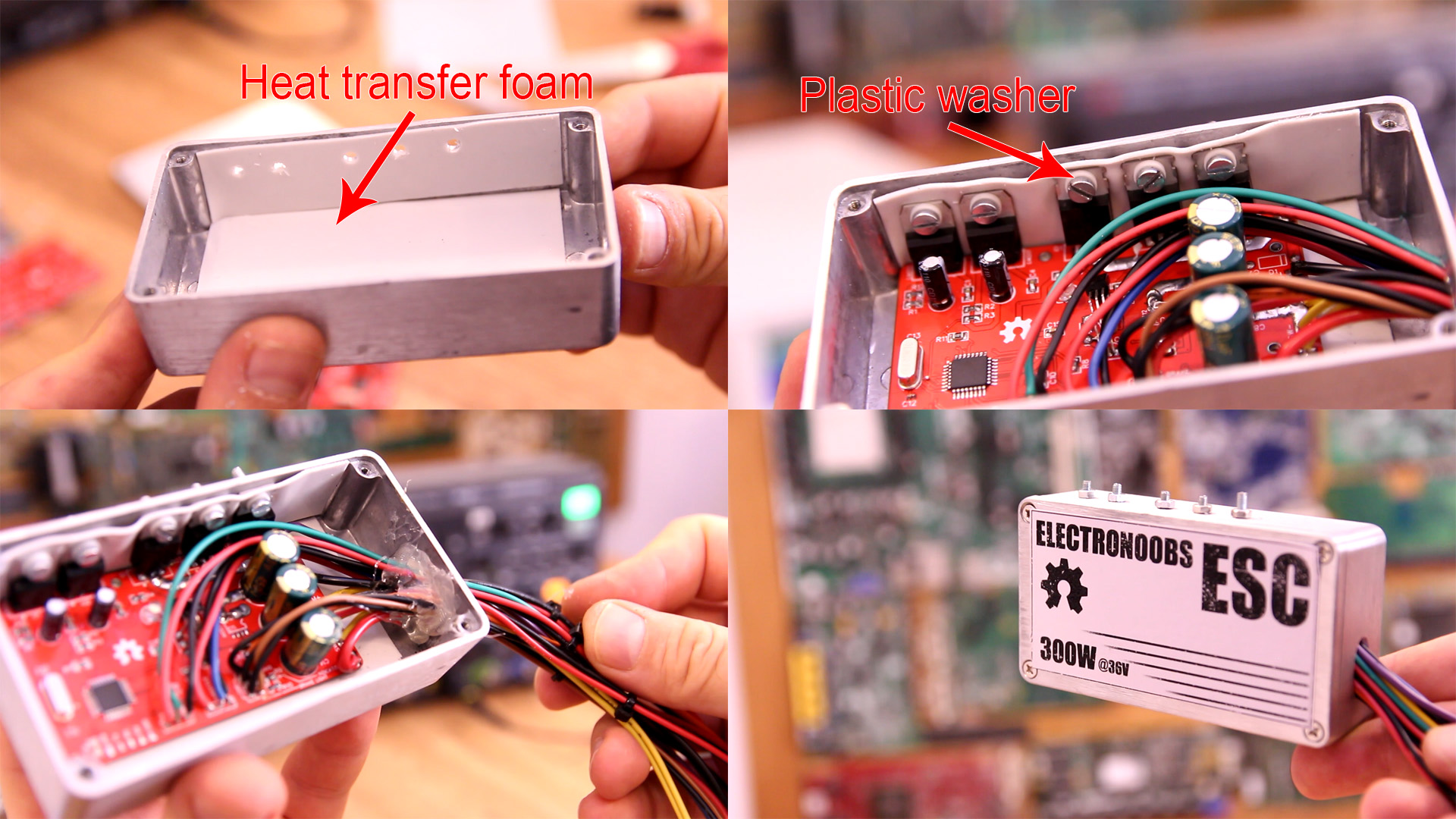
The case is as important as the PCB. Without a good heat dissipation, the MOSFETs would burn out in seconds. So, I will use this small metal case below. Measure and make the holes. Then I add some heat transfer paste between the MOSFETs and case but also below the PCB so it won't touch the case and create a short circuit. Once insulated, add the screws. Use a plastic washer for the screws so they won't touch the metal part and create short circuit. Add all wires, make a hole, pass the wires and glue them in place. Close the case and add label. That's it.
I hope that you like this tutorial. If you consider supporting my work, buy my PCBs on my shop, or maybe consider supporting me on PATREON or if you want, make a PayPal donation. Thank you very much.