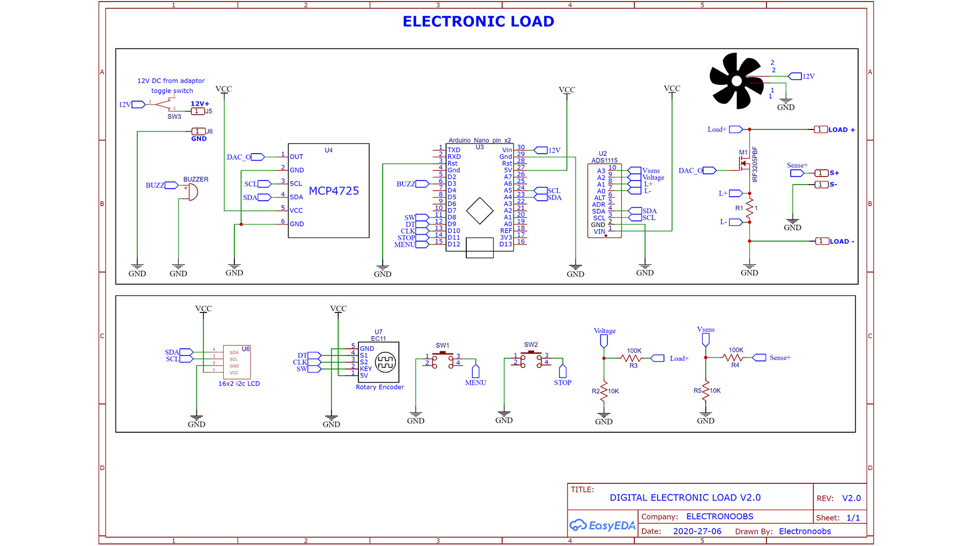
• Let's talk about the schematic. Is important and you might need to adapt it to your needs. First of all, 12V from the DC adaptor is connected to a toggle switch and then to the Arduin o Vin pin and the fan so when we toggle the switch, everything is powered on. The NANO has a 5V regulator and that will be our Vcc. Supply all modules to Vcc and GND and connect the SDA and SCL pins from the Arduino to all i2c modules (ADC, DAC and LCD).
• Connect the encoder to Vcc, GND and the 3 pins to digital pins D8, D9 and D10 of the Arduino. Connect the push buttons to pins D11 and D12. Also connect the buzzer to D3 for PWM signal for tones.
• About the voltage divider. Please read the code and the next parts of the tutorials. I've used 10K and 100K but those are not exactly these values so we need to adapt the multiplier in the code. Read the code.
• To read the current I use a 1ohm shunt. We read the voltage on this load in differential mode with the ADC. Again, this resistor is not exaclty 1ohm, so the multiplier will be adapted in the code. Read that part later. Connect the DAC output to the gate of the MOSFET. Load+, Load-, S+ and S- are the banana connectors we haev on the front panel. That's it.
If you want the controller to go more than 2.1A, you will need more voltage at the MOSFET gate then 5V that the DAC could give. For that use this second schematic with an OPAMP between the DAC and the MOSFET gate.