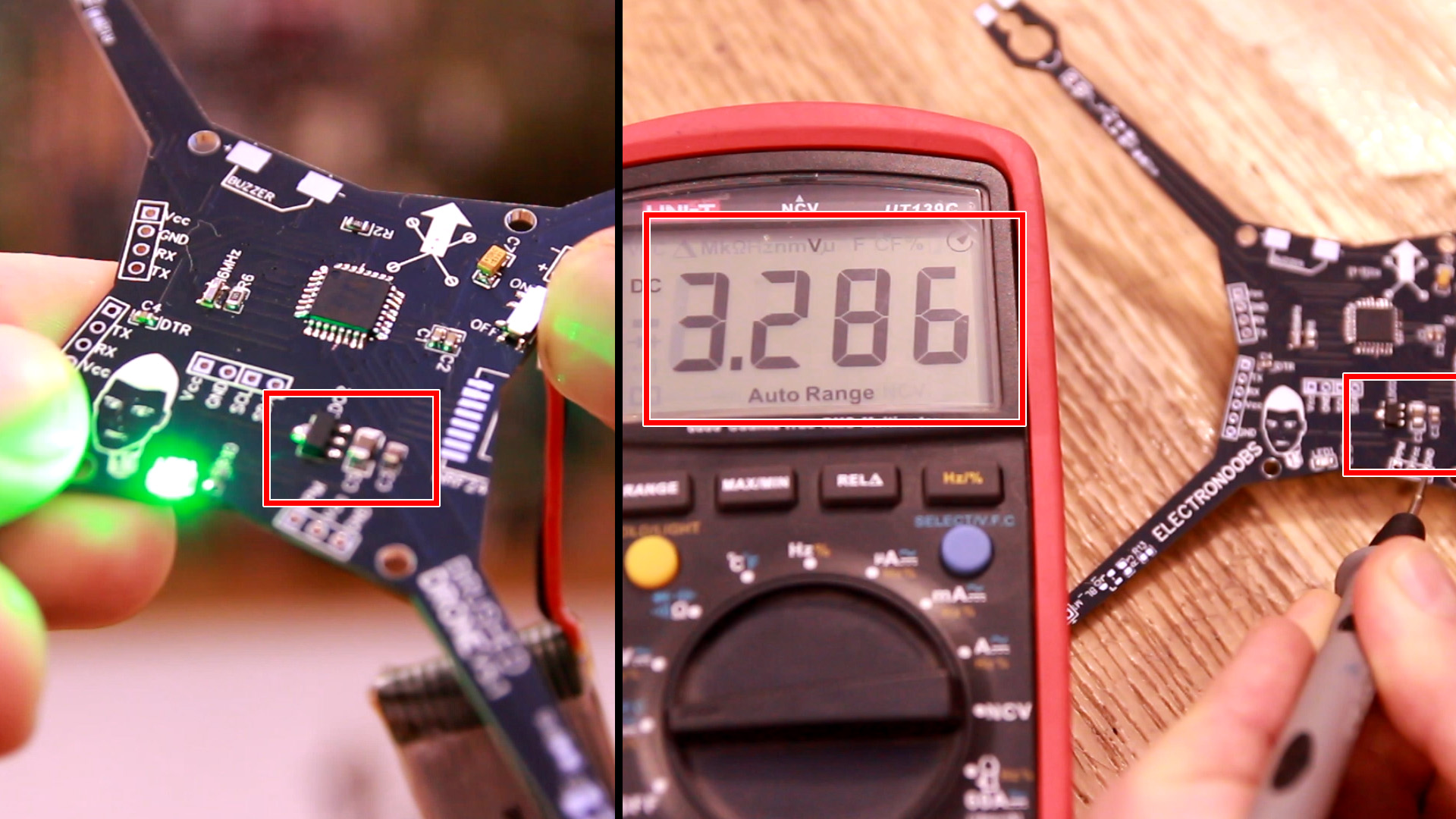
Ok, at this point we know the microcontroller works. Before we solder the rest of the components, we must make sure we have a good 3.3V voltage, otherwise we will burn the NRF24 radio module because it can't take higher voltage than that. So, solder the HT73-33 LDO and also the 10uF and 100nF capacitors at input and output. Also solder the input pins and the slide switch. Extra: I've also sodlered the LED and R10 resistor of 330R. Then connect the 3.7V battery at the input pins and flip the switch. Check the voltage at the NRF24 pins with the multimeter. It should be close or exactly 3.3V. If is higher, it might create problems so check the connections. Now that we have our 3.3V, we can solder all the other components.
You can now solder all the other components but follow this order: You must solder the MPU6050 last because otherwise, you won't be able to access the components below. Solder the MOSFETs, diodes and resistors on each arm for the motors control. Then solder the rest of resistor and capacitors. Solder the NRF24 radio module and finally the MPU6050 on top. You could always add more i2c modules on top such as magnetometer or barometer.
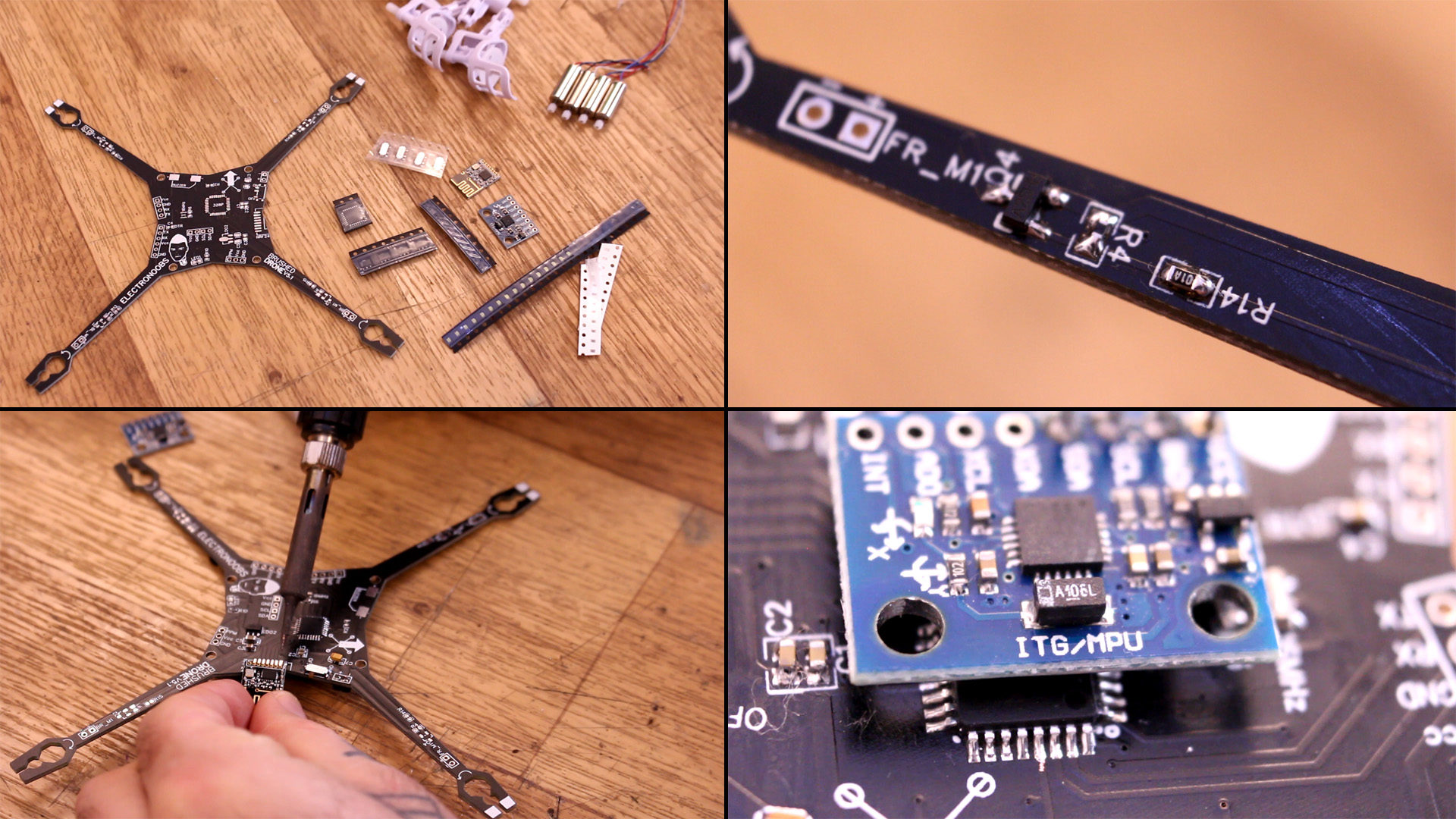
All components are soldered. Let's add the motors. First we glue the supports. Make sure the propeller shaft is facing upwards. Add super glue and fix each support in place. Insert the DC motors and then solder the wires to the + and - pads for each motor.
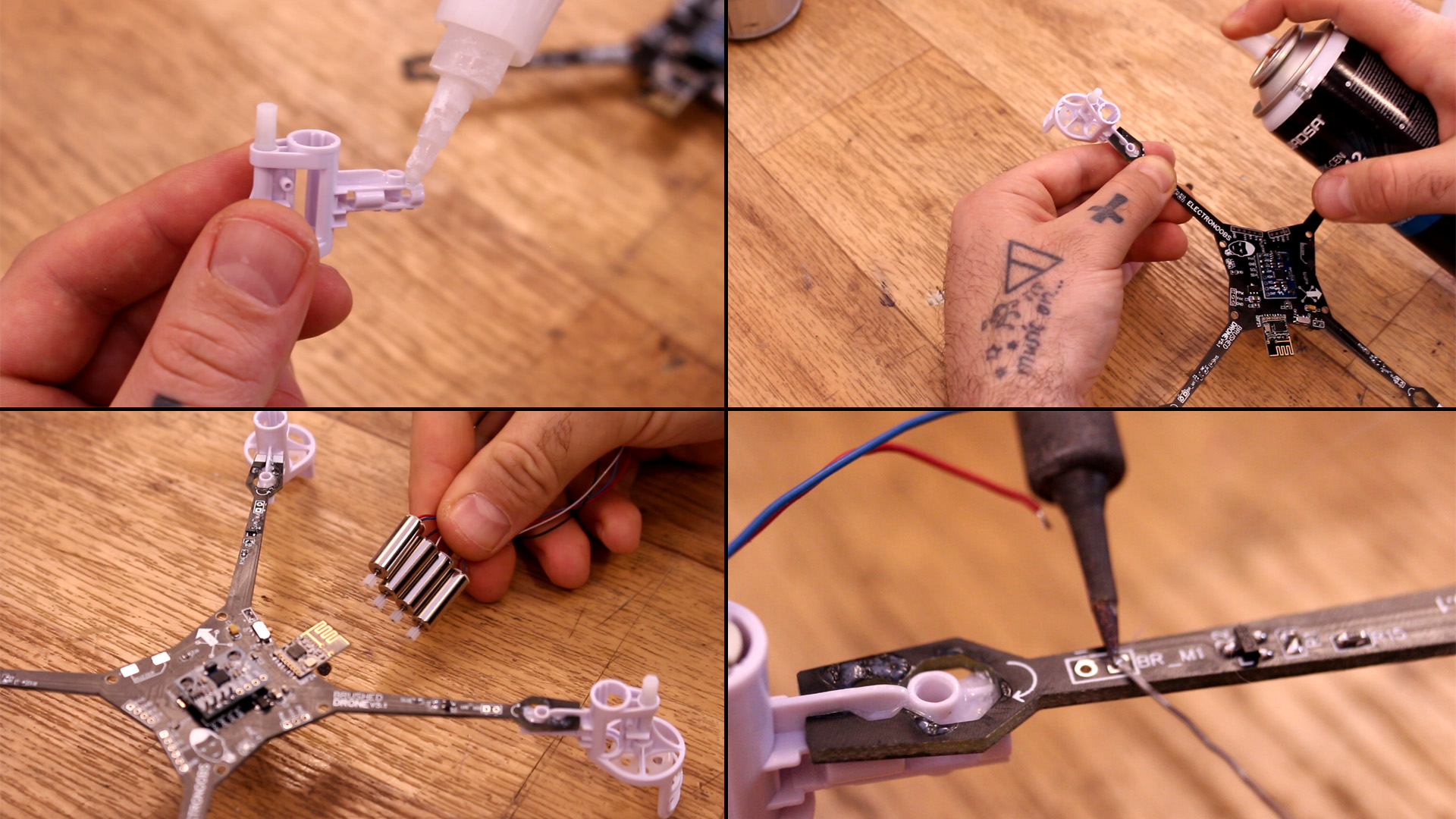
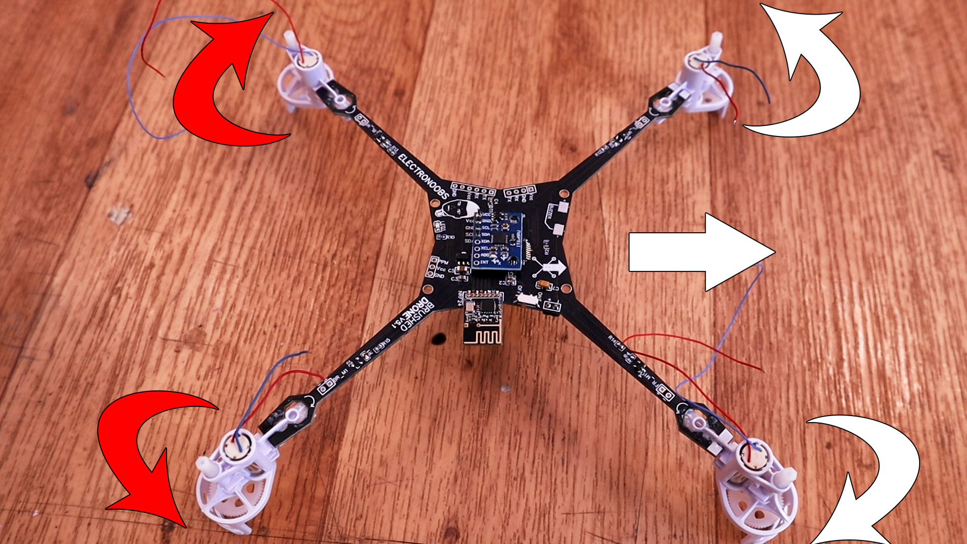
Soldering the motors well is very important. Use an external power supply set to 3.7V in order to check in which direction the motor will rotate. Once you knwo which polarity will rotate in which direction, solder the wires to + and - in such a way taht the motors will spin like below. The main arrow shows the front face of the drone. Then, the propellers will rotate outwards like below and that's important for stability and yaw control.
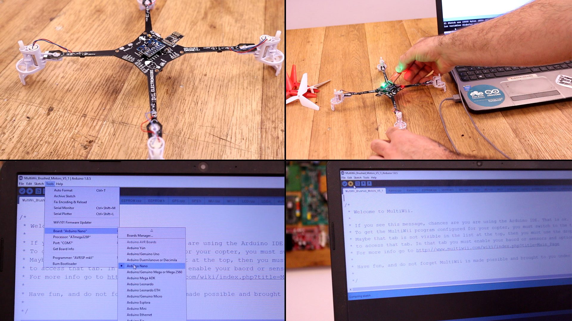
Ok, now the drone is ready. Don't connect propellers yet! Go below and downlaod the multiwii code. Open that code in Arduino IDE. Connect the FTDI programmer to the PCB. Compile and upload the code. The code is not the usual MultiWii code. Is adapted to work witn NRF24 radio connection and to contero brushed mosfet with PWM signal instead of ESC control. So, not any MultiWii version will work, only the code below.
Now the drone has the MultiWii code. We have to test it. Go below and download the MultiWii Java platform. Make sure you have Java installd on your PC. Run the Multiwii platfrom for 32 or 64 bits. Keep the PCB connected to the programmer with USB. In the app, select rhe com of the FTDI programmer and click start. Now you should see the data from the drone as in the video below. Calibrate accelerometer. If at this point you have the radio controller ready, test if you receive data as well.